

🎓 Dr. Freemo  🇳🇱
@freemo@qoto.org
🇳🇱
@freemo@qoto.org
- Keybase
- freemo
- UFoI Member
- http://UFoI.org/u/freemo/
- Website
- http://JeffreyFreeman.me
- Gitlab
- https://git.qoto.org/freemo
Admin
Jeffrey Phillips Freeman
Innovator & Entrepreneur in Machine Learning, Evolutionary Computing & Big Data. Avid SCUBA diver, Open-source developer, HAM radio operator, astrophotographer, and anything nerdy.
Born and raised in Philadelphia, PA, USA, currently living in Utrecht, Netherlands, USA, and Thailand. Was also living in Israel, but left.
Pronouns: Sir / Mister
(Above pronouns are not intended to mock, i will respect any persons pronouns and only wish pronouns to show respect be used with me as well. These are called neopronouns, see an example of the word "frog" used as a neopronoun here: http://tinyurl.com/44hhej89 )
A proud member of the Penobscot Native American tribe, as well as a Mayflower passenger descendant. I sometimes post about my genealogical history.
My stance on various issues:
Education: Free to PhD, tax paid
Abortion: Protected, tax paid, limited time-frame
Welfare: Yes, no one should starve
UBI: No, use welfare
Racism: is real
Guns: Shall not be infringed
LGBT+/minorities: Support
Pronouns: Will respect
Trump: Moron, evil
Biden: Senile, racist
Police: ACAB
Drugs: Fully legal, no prescriptions needed
GPG/PGP Fingerprint: 8B23 64CD 2403 6DCB 7531 01D0 052D DA8E 0506 CBCE
Joined Jul 2018
@Electronics
This is either a 250kW Automatic Tuner, or they take their Irish Whiskey production very seriously.
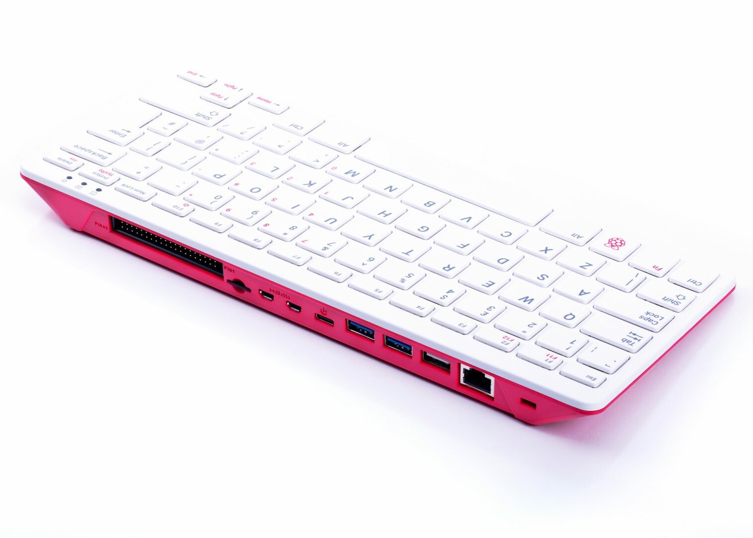
I feel like this is how the Raspberry Pi should have been packaged from day one, just built directly into a keyboard.
#Electronics #RaspberryPi #Computing #Technology
QT: https://bananachips.club/@nev/105141979429842923
Holy shit y'all. A Raspberry Pi in a keyboard, $100, just add monitor. Waaaaaaaant. https://www.raspberrypi.org/blog/raspberry-pi-400-the-70-deskto...
Wanted to share my prototype design for the #ROES meter with the Electronics Group.
About a month ago I sent the boards off to be printed for a prototype run and recently got them in. So V2.0 is soon to be officially released (though I may do a minor revision before printing up a large number of boards).
Attached are some screenshots of the final schematic and some renderings of what the boards will look like when its done. Its a 4 layer board though so many of the traces are internal.
You can find the files for this, which will be released as open-source, here:
https://git.qoto.org/roes/roes-hardware/
#Ham #HamRadio #Radio #RF #EE #Electronics #ElectricalEngineering #Science
I wanted to share my favorite circuit simulator to the electronics group. It isnt the most advanced and it wont replace professional tools. But its great at modeling semi-ideal components with an epic way of visualizing current and voltage that just makes it an amazing tool at getting a feeling for how circuits actually work.
Everyone should check it out and play with it, you wont regret it.
Hello everyone welcome to the group. I’ll kick it off with some pictures of a style of protoboard I absolutely love. Its great for RF stuff and even if it isnt rf, lets face it, SMD is better!
Anyone out there who is entry-level in electronics or even just a hobbyist with no expiernce want a job? Its a sales job though, which is why you dont need really good electronics expiernce, but there is room to do actual EE too if that's your end goal.
Send a DM if interested.
I cant help but feel it would cost almost as much to build this fake as it would to just build the capacitor the correct way....
A picture of a Radio Shack circa 1950. Its a shame self-repair is virtually non existent and shops like this and radio shack themselves, are quickly disappearing. I remember when I was younger you could go there and any electronics part you could imagine. Now they cant even give away what little inventory they have.
FYI to all my Electronics people out there.
Did you know you can represent capacitance and inductance with a complex number and by doing so you would incorporate ESR (equivalent series resistance) into your equations. Essentially you dont have to model with idealized components and add in the parasitics manually, you can add the parasitics directly into the capacitance or inductance of your components!
See the following equation in my blog and the subsequent explanation if you want some further details and examples: http://jeffreyfreeman.me/an-indepth-look-at-duals-and-their-circuits/#mjx-eqn-realcap
#electronics #electricalengineering #EE #HamRadio #AmaetureRadio #Physics #Science #QotoJournal
My article is finally up on reddit (had trouble getting the moderators to approve it for some reason). As a result it hidden for over a day. Any of you who are redditors check it out over there and if you like it give it some love.
#Electronics #EE ##RF #HamRadio #AmateurRadio #Science #Physics #Math #Maths #mathematics
For those of you who enjoyed my recent blog post on Circuit Duals and Magnetic Circuits I have now compiled a version of it in PDF if you want to keep a local copy or have it for reading on on an e-reader. Feel free to distribute the link.
https://drive.google.com/file/d/1fECh_IeFYBHoFuaw08zO2dkluZPunkP7/view?usp=sharing
For those of you who are just now hearing about it the article describes the idea of Duality in math, how it applies to circuits, how to calculate duals for systems of equations, and a few examples of circuit duals. It also goes indepth on magnetic circuits as a dual of electric circuits. There is an interesting blurb at the end about how to extract energy from permanent magnets as well.
If you prefer the more colorful blog link instead, which will also be the only place I make corrections or update it most likely, the link for that is as follows:
http://jeffreyfreeman.me/an-indepth-look-at-duals-and-their-circuits/
#Electronics #EE ##RF #HamRadio #AmateurRadio #Science #Physics #Math #Maths #mathematics #qotojournal
So two weeks working on this article about Circuit Duals and Magnetic Circuits and it is finally finished and published! Check it out!
Its about mathematical duals and how they relate to electric circuits. I cover several common circuits as duals and how to calculate duals. Bu I also describe a rarely known type of circuit dual called a magnetic circuit that uses the magnetic field instead of an electric field to do all the things an electric circuit can do and explain magnetic inductors and capacitors. It's pretty cool stuff, I even touch on how you can extract energy from the magnetic field of a permanent magnet to power a magnetic circuit (or an electric circuit for that matter.
http://jeffreyfreeman.me/an-indepth-look-at-duals-and-their-circuits/
#Electronics #EE ##RF #HamRadio #AmateurRadio #Science #Physics #Math #Maths #mathematics #QOTOJournal
Ok I think my article will be ready to be published tomorrow after I do one more re-read in the morning.
In the meantime I'd really appreciate anyone giving it a read and seeing if they find any errors please. I really could use some final eyes on this before I publish it live!
You can suggest edits direct on my repo or here, I will be happy to give a thank you link at the bottom to anyone who helps.
n the source for my blog:
Its about mathematical duals and how they relate to electric circuits. I describe a rarely known type of circuit dual called a magnetic circuit that uses a magnetic field instead of an electric field to do all the things an electric circuit can do and explain magnetic inductors and capacitors. Its pretty cool stuff, I even touch on how you can extract energy from the magnetic field of a permanent magnet to power a magnetic circuit (or an electric circuit for that matter.
#Electronics #EE ##RF #HamRadio #AmateurRadio #Science #Physics #Math #Maths #mathematics
Help! From anyone interested in English, Physics, Math, or Science.
I have written a rather massive article in the hopes of teaching people with mid-level knowledge in electronics about the idea of Duals in mathematics, how that applies to circuits and the various types of circuit duals that exist
I also include a great deal of detail in the end about one very obscure and rarely studied circuit dual called the magnetic circuit dual, it is a circuit, like a magnetic circuit, but instead of current being the flow of electrons, it is the flow of a magnetic field through wires made of iron instead of copper.
I even touch on briefly how one can extract energy from permanent magnets and other details most people arent very familiar with.
The problem is the article is massive and I really could use some eyes on it. Whether its just to try to help me catch english mistakes, or if your not that experienced perhaps tell me the parts that are confusing, as I would like this to be accessible to people who may not be scientists and only know entry level electronics or science. any feedback from anyone at any level would be highly appreciated.
Keep in mind I couldn't find many good sources laying out the equations for magnetic circuits very clearly so I had to derive a lot of the equations myself, though the concept is well established as fact and many peer-reviewed papers have been written on it. But bear in mind there may be minor errors in my math as well, so that too needs some criticism, though the math should be fairly close to correct.
Anyway any input from anyone would be much appreciated.
The draft of the article can be found on the beta site for my blog, here is a direct link:
http://beta.jeffreyfreeman.me/an-indepth-look-at-duals-and-their-circuits/
Similarly if you find any mistakes you can message me here, or you can leave a merge request on the repo for the article, here is the direct link to the markdown file in the source for my blog:
It is much prefered that if you have specific edits like english or math you do it as a pull request as it can be a huge pain for me to hunt down the specific part of the text you are referring to if you point out mistakes as replies here. However if your unwilling to do a merge request please still ping me here as I'd rather know than to just let it go unnoticed.
Anyone who helps I will add a thank you with your name and a link to your own site at the bottom of the article if you wish, this might help draw some traffic to your own site.
#Electronics #EE ##RF #HamRadio #AmateurRadio #Science #Physics #Math #Maths #Mathematics #English
I have been writing a blog article that is getting so big its a small text book at this point. Easily the biggest and more detailed blog article on a subject I have ever wrote.
The topic is Duals of Electrical circuits.
It takes me half the paper to even get to electronics, I start by trying to describe what a dual is in general terms, give simple mathematical examples, then go onto duals of systems of equations where I finally tie it into electrical circuits.
At that point I dive into a series of examples of different types of duals for electrical circuits, and then finally end with describing a magnetic circuit as a dual for an electric circuit, where the power sources become magnets, the copper wires are replaced with iron ones, electrical current is replaced with magnetic current (which is a propagating magnetic field), and then I explain each magnetic dual for each discrete component like capacitors, inductors, resistors, and transformers. Needless to say this thing gets really deep really fast.
If your interested in seeing the final result keep an eye out on my blog, should be released any day now.
http://jeffreyfreeman.me/an-indepth-look-at-duals-and-their-circuits/
#Electronics #EE ##RF #HamRadio #AmateurRadio #Science #Physics #Math #Maths #Mathematics
As you all know the earth is a giant magnet. As a giant magnet antarctica would be the north or south pole of that magnet?
So I just provided the answer to this Stackexchange question and I noticed something kinda cool and interesting in the final equation:
The equation, for those of you on a Latex capable instance is:
\( k \cdot \frac{N_p}{N_s} \cdot \sqrt{\frac{L_s}{L_p}} = R_\phi\)
In this case R, the flux linking ratio, must be a value between 0 and 1 and represents the percentage of flux that is mutual between two coupled inductors (a transformer).
Similarly k is Coefficient of Coupling, which is also a ratio between 0 and 1. It is a different measure of how well coupled two inductors are.
What I find interesting about the equation is that all the other variables can be anything from 0 to infinity, so at first glance you would think that it would be possible to have a scenario where either R or k are greater than 1. But in reality because the number of windings of the primary and secondary have a reciprocal relationship to that of the square root of the ratio of the inductances, in reality any real world values that you could plug in here would actually never be able to produce a contradiction.
If you look at the equation to calculate the inductance of an inductor based on its number of turns this becomes obvious. for simplicity if we assume the diameter if the inductor and the wire thickness are all the same then the relationship is basically the following:
\( L = N^2 \cdot C \)
Where L is the inductance, N is the number of turns, and C is some constant. So essentially the square of the number of turns of the inductor is linearly proportional to its inductance. Going back to the equation I was talking about this basically counters the sqrt function in the equation and it becomes obvious why any real world values would always satisfy the equation correctly.
#Electronics #ElectricalEngineering #EE #Math #Science #Physics #Maths #Mathematics
A fun article I just wrote explaining what the Reflection Coefficient is and how it can be used:
http://jeffreyfreeman.me/understanding-the-reflection-coefficient/
#Electronics #RF #Radio #Maths #Math #Mathematics #Physics #HamRadio #Ham #AmateurRadio
- Keybase
- freemo
- UFoI Member
- http://UFoI.org/u/freemo/
- Website
- http://JeffreyFreeman.me
- Gitlab
- https://git.qoto.org/freemo
Admin
Jeffrey Phillips Freeman
Innovator & Entrepreneur in Machine Learning, Evolutionary Computing & Big Data. Avid SCUBA diver, Open-source developer, HAM radio operator, astrophotographer, and anything nerdy.
Born and raised in Philadelphia, PA, USA, currently living in Utrecht, Netherlands, USA, and Thailand. Was also living in Israel, but left.
Pronouns: Sir / Mister
(Above pronouns are not intended to mock, i will respect any persons pronouns and only wish pronouns to show respect be used with me as well. These are called neopronouns, see an example of the word "frog" used as a neopronoun here: http://tinyurl.com/44hhej89 )
A proud member of the Penobscot Native American tribe, as well as a Mayflower passenger descendant. I sometimes post about my genealogical history.
My stance on various issues:
Education: Free to PhD, tax paid
Abortion: Protected, tax paid, limited time-frame
Welfare: Yes, no one should starve
UBI: No, use welfare
Racism: is real
Guns: Shall not be infringed
LGBT+/minorities: Support
Pronouns: Will respect
Trump: Moron, evil
Biden: Senile, racist
Police: ACAB
Drugs: Fully legal, no prescriptions needed
GPG/PGP Fingerprint: 8B23 64CD 2403 6DCB 7531 01D0 052D DA8E 0506 CBCE
Joined Jul 2018
