
this is an aircraft avionics mystery! it's made by Bendix, but i have no part number because the cover is missing (bought it this way from our local electronics flea market). as this video shows, i got it to work, and this thread explains how...
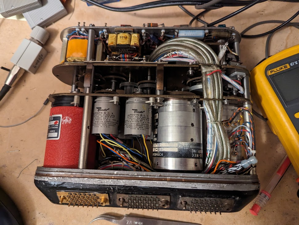
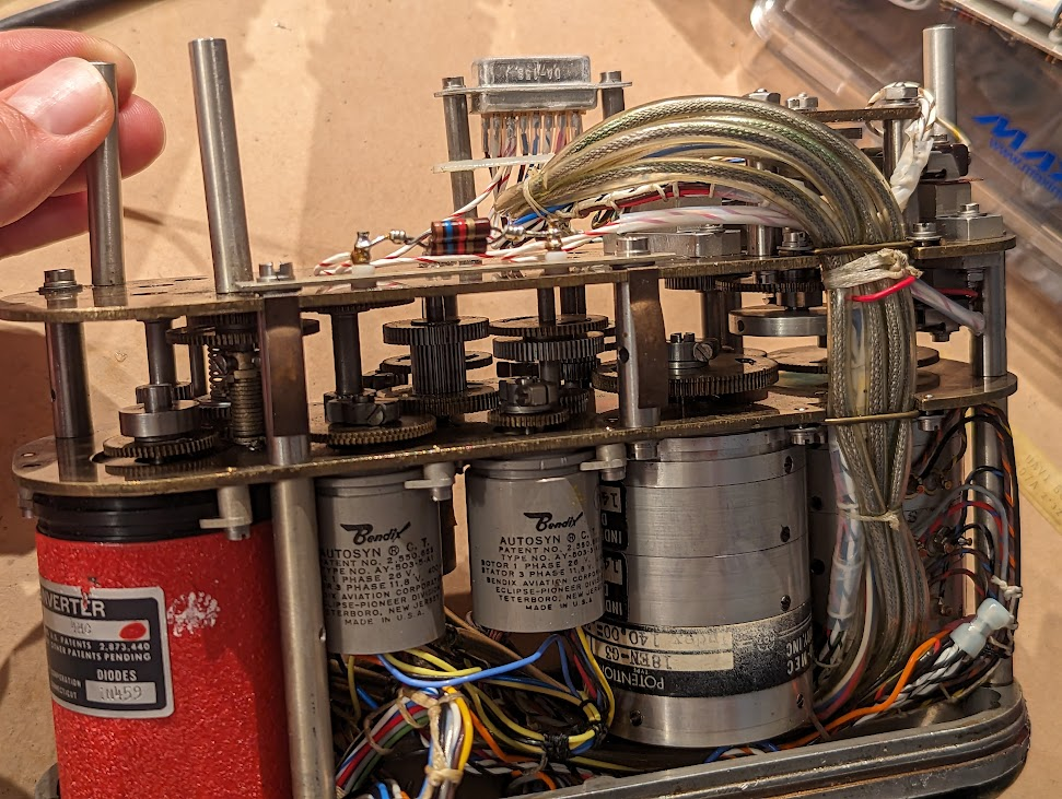
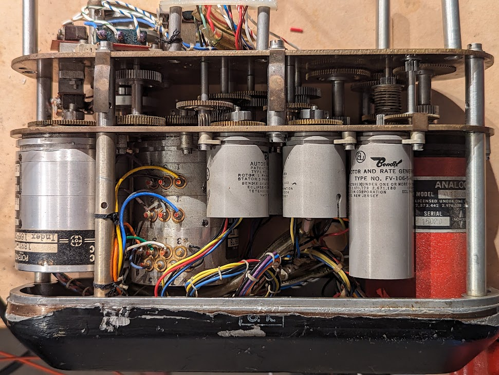
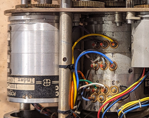
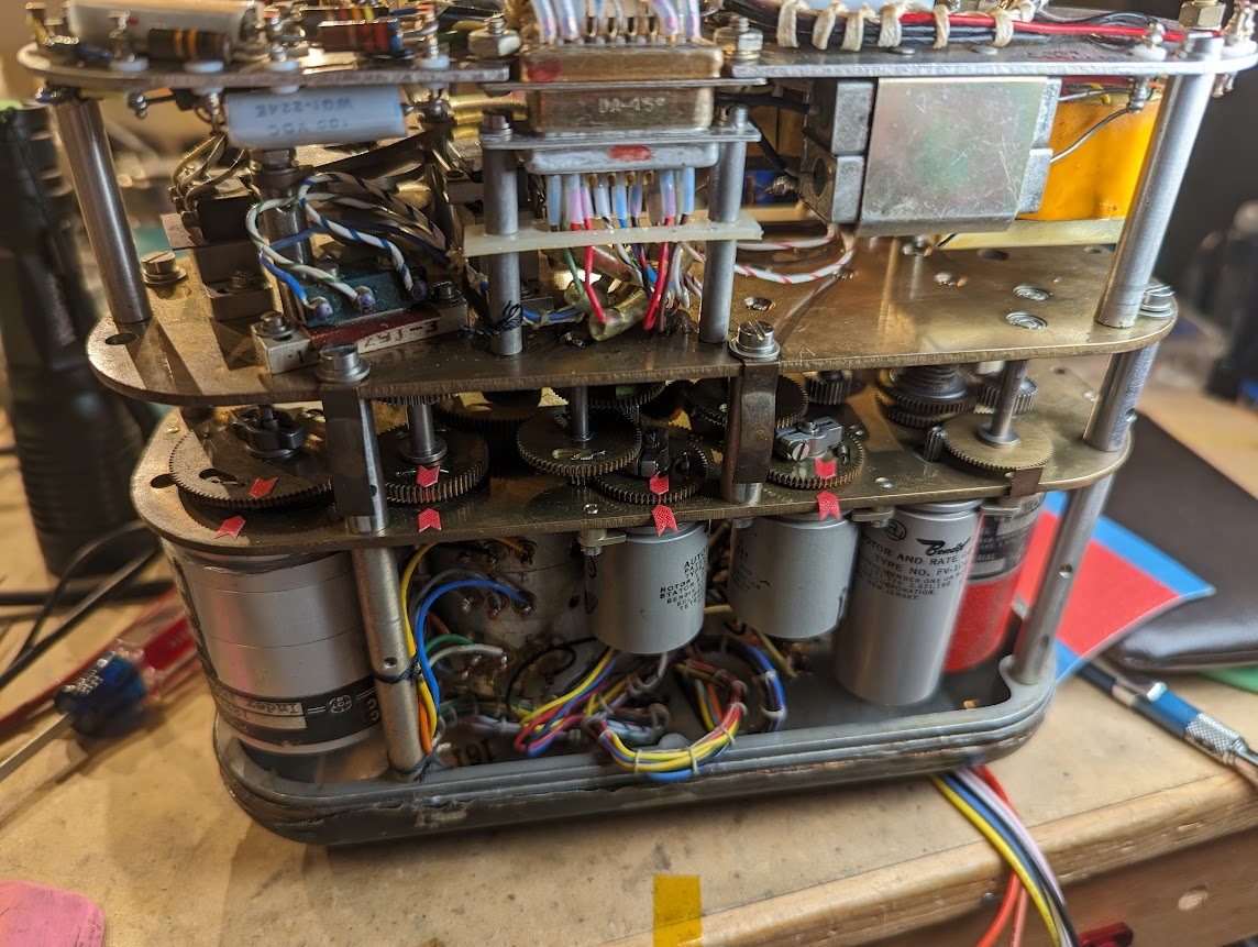
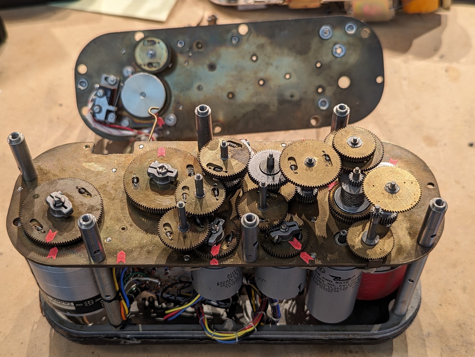
there are 3 26-pin connectors. there are four synchros inside, a motor, a "digital analog converter", and two large potentiometers. there's also a gear train and an electronics module on top.
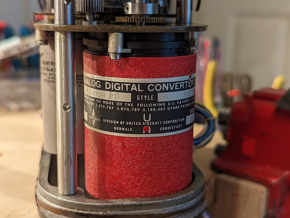
closeup of the Digital Analog Converter. based on the patent numbers, it appears to use a system of brushes to convert the shaft position to a set of parallel bits.
on the other side of the unit you can see two more synchros as well as a "motor and rate generator" which is basically just a motor with an extra winding that generates a voltage proportional to the motor speed.
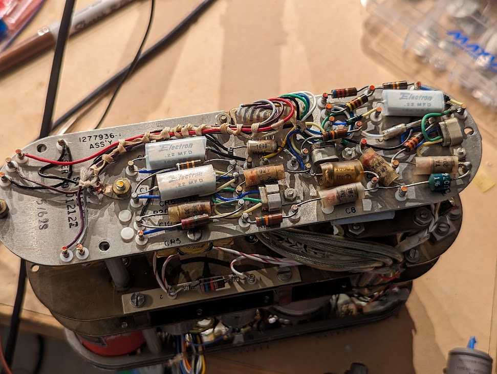
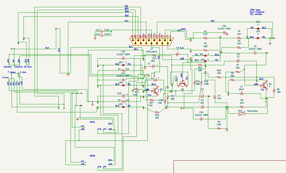
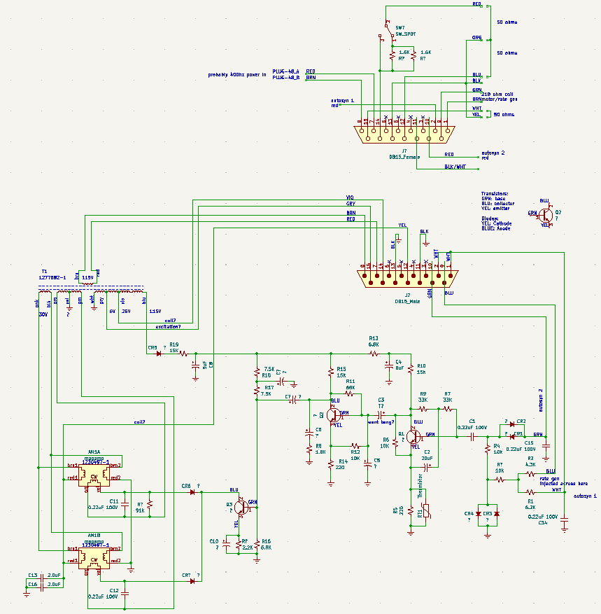
the electronics module has a number of transistors, resistors, capacitors, and other components.
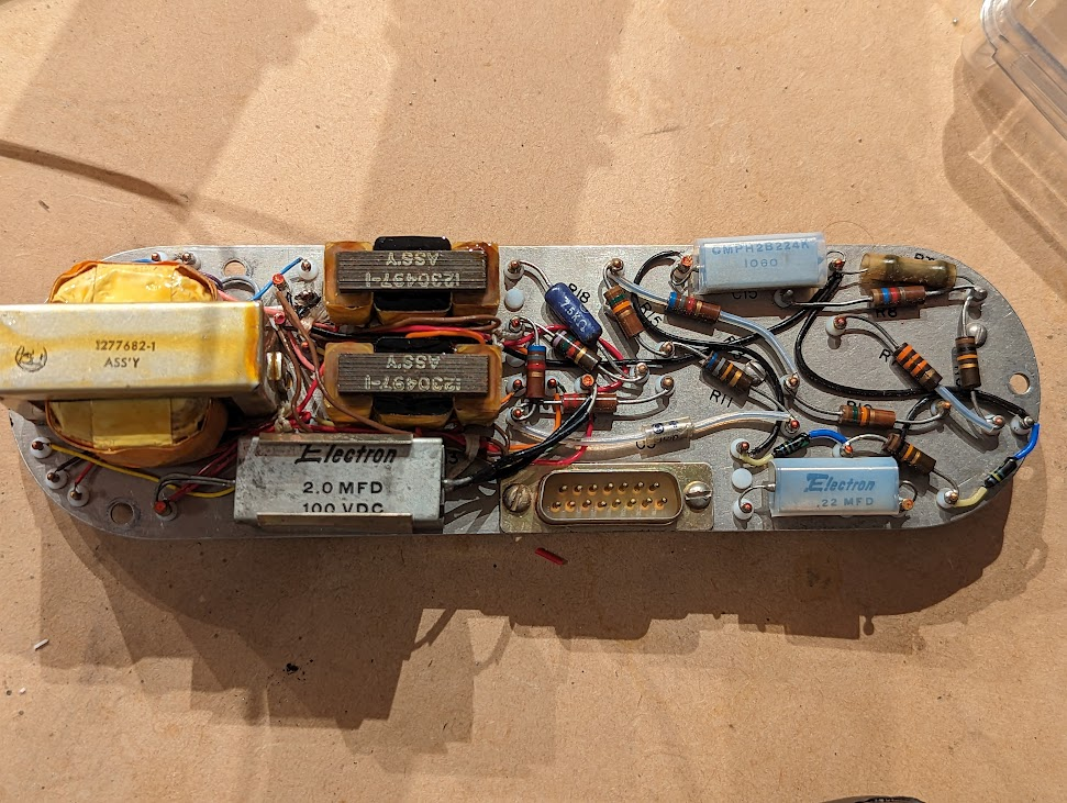
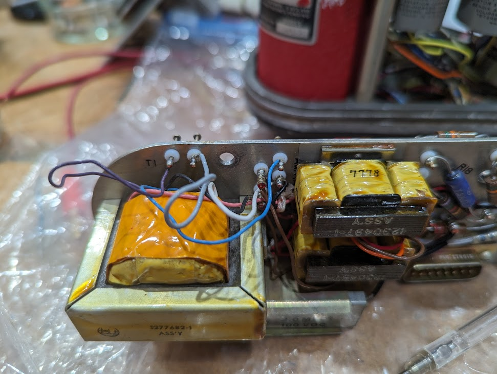
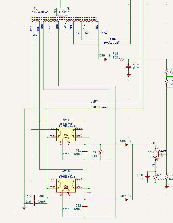
the electronics module is connected to the rest of the unit with a 15-pin D-sub connector, so it comes apart easily. on the other side, you can see a transformer on the far left, and next to it are two magnetic amplifiers!
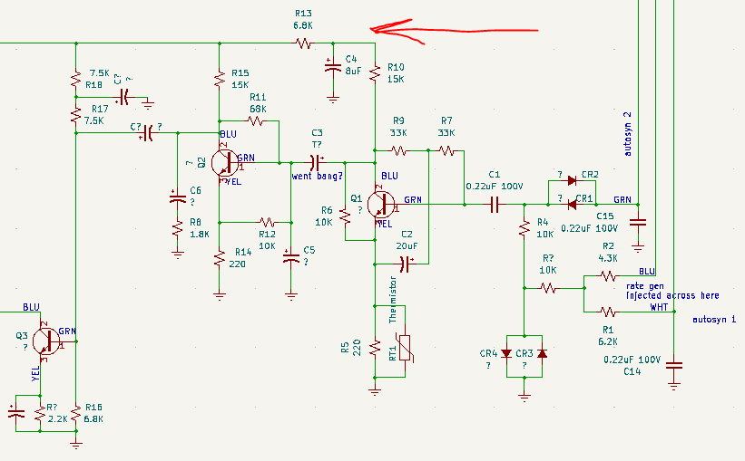
i spend a few hours puzzling over the electronics module and reverse engineered a schematic. this is step 1, which matches closely with the physical layout.
i compared notes with @kenshirriff who has been reverse engineering a Bendix Air Data Computer: https://oldbytes.space/@kenshirriff/110578423219847109
many of the components are identical between the two units, which is why i think mine is also made by Bendix.
in fact, the magnetic amplifiers it uses are exactly the same. Ken wrote a very nice article about magnetic amplifiers for the IEEE Spectrum, so i won't explain it again: https://spectrum.ieee.org/the-vacuum-tubes-forgotten-rival
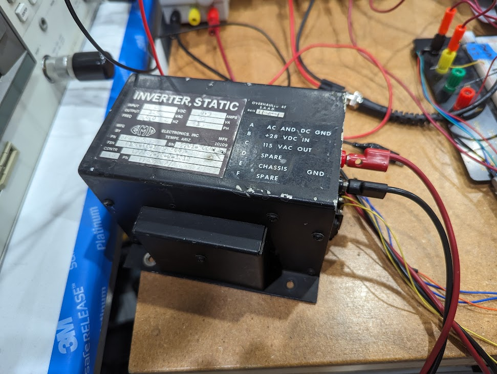
i wasn't sure what sort of power the module needed. maybe 28VAC at 400Hz? i teased out and disconnected a bunch of wires on the large power transformer, fed in 28V to the suspected input wires, and measured the outputs.
even if the input voltage is supposed to be higher, the ratio of the voltages will remain the same. in this case, the output voltages only made sense for an input of 115V.
Marc has an inverter that can turn 28VDC into 115VAC at 400Hz, but he's on vacation and i've been working on the project from home. so what to do?
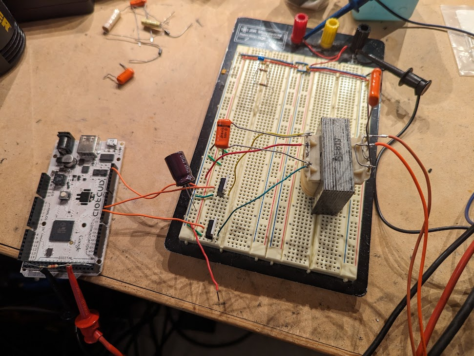
i built my own inverter, natch! this is a junk box 115V transformer with a 12V center tap output. it turns out to work fine at 400Hz. i'm supplying DC to the center tap and there are two MOSFETs each with the drain connected to the remaining two terminals. this is essentially a resonant Royer design, but the MOSFETs are being driven by an Arduino that tries to PWM two half sine waves. it's bad but it works!
the basic idea of this device is that you feed in two sets of 3-wire synchro signals, one coarse and the other fine. they are presumably from some kind of sensor.
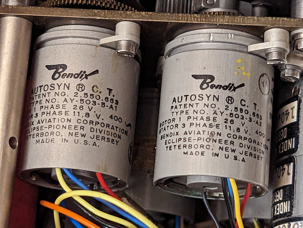
these synchro signals get fed into a pair of autosyns--a device that generates an error signal proportional to the difference between the input electrical angle and the mechanical shaft angle.
the error signals enter this transistorized amplifier circuit. there's some filtering, limiting, and a bit of the rate generator signal is mixed in (maybe as a differential gain term?) but basically it just makes a small signal much larger.
the last stage of the transistor amplifier drives the two mag amps, which are cross connected so that one runs the motor in one direction while the other runs the motor in the opposite direction.
depending on when the transistor turns on (due to the phase of the signal from the autosyns) it will turn on one or the other mag amp.
(the schematic here might have swapped wires on the mag amp outputs, so ignore that)
to sum up: the whole gear train (which is all connected together) gets rotated by the motor so that both the coarse and fine autosyns match the input signals coming from the external sensor's pair of coarse and fine synchro senders.
OK--so our external sensor has a mechanical position, and now we've duplicated it inside this avionics box. what now?
the gear train connects to several other things: 1) another pair of synchro senders, which produce a buffered version of the sensor input (another set of six output wires).
2) a "Digital Analog Converter" which presumably converts the mechanical position into a digital signal. (i need to take it apart at some point!)
3) a set of two potentiometers, each of which have multiple ganged taps. i haven't tracked down where all this wiring goes yet.
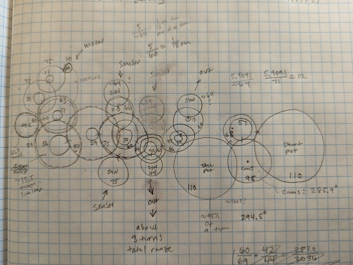
i've been figuring out the gear train and counting teeth for...a long time.
here's my horrible diagram. looks like the full range of motion between the hard stops is 294.5 degrees on the potentiometers. oddly enough, the fine INPUT synchro turns 1 full turn for 0.8500 of a turn on the OUTPUT fine synchro!
full range on the coarse input synchro is 101 degrees (it can't move a full turn). for the output coarse synchro, it is 85 degrees.
also strange is that the gear reduction between the coarse and fine synchros appears to be 12:1. that's not really a standard ratio--equipment typically uses 9:1, 18:1, 27:1, or 36:1.
I just can't emphasize it enough: jet-age aircraft ran on clockwork. straight up steampunk what with the little brass gears and vacuum tubes and neatly-tied bundles of colorful wire


