
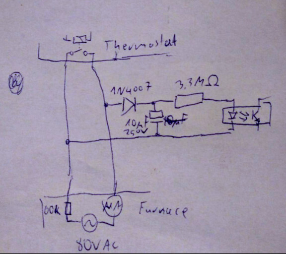
Looks like the control line for my furnace is 80V AC and the thermostat shorts it (with a relay) to turn on the heating.
I'd like to make an ESP32 detect whether the heating is on, so I guess an optoisolator in parallel to the thermostat? With a 4k resistor for 20mA through the LED?
I'm open to advice.
Or, I should say, please tell me if this is a good idea or a bad idea.
although I don't know if there are optoisolators that can withstand 80V of backwards voltage....
If it's AC maybe I should use a transformer? To step it down to like 8V AC or sth...
Per Piggo's advice, I decided to rectify that 80V before passing it to the optoisolator.
In the meantime I took a 4.7k resistor in series with an ammeter, and connected it to that 80V, to see what kinda current it'd give me.
It gave me 1.2mA... and turned on the heating. So the furnace must have a 60k-ish resistance inside it. That means I need a much bigger resistor and much smaller current, begat the question: will an optocoupler even detect that?
1/
I bought a PC817 optocoupler, which is fairly popular. It's datasheet specifies current transfer factor only down to 1mA input current, so I had to test myself what happens below that.
It appears that at 35uA through the diode (input), I get 1uA through the phototransistor (output).
Not exactly an amplification, but at least it's something.
Now to figure out if this is something ESP8266 can detect
(yeah turns out I have ESP8266 not ESP32)
Looks like 300uA is enough to turn on the furnace, so that 35uA through optocoupler's diode seems far enough from that...
I don't have a 3.3M (or even 1M) resistor to check if 1uA is enough for a GPIO though...
I'm guessing 1uA will be very prone to interference but I'm gonna try anyway lol
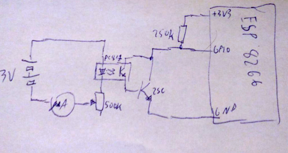
Ok, so it appears that a 1M pull-up resistor is too much for the ESP's GPIO, and so is 500k, but 250k is fine.
That means I'd need around 10uA to flip the GPIO.
With the PC817 optocoupler, that requires 100uA on the input, which is IMO kinda close to the 300uA that turns on the heating... I'd much rather pull only 30uA from the furnace's control line.
If I had a darlington optocoupler, like an LTV-355T that would probably solve all my problems, but they don't have it in the nearby store. I'll check another store.
If I don't get an LTV, I'll try adding a separate transistor after the optocoupler to amplify the signal.
Basically it'd be the same schematic as the LTV but the second transistor wouldn't be inside the optocoupler, so more room to pick up interference. We'll see how it goes...
I didn't have time to go to the other store but I found a random 2SC1815 transistor laying around.
Measured its hFE, it was 166, so I figured I may as well try adding it as an emitter-follower to the PC817 optocoupler.
Lo and behold, I can totally detect 35 uA through the optocoupler's LED (which was 1uA through the phototransistor last time I checked).
I can even detect 10uA through the LED, resulting in a nice 0.7V low state on ESP's GPIO.
Now I just need to replace the battery+pot test setup with a 3.3M resistor connected to that 80V of the heating control line, and should be all good?
oh, no, I also need a rectifier and a capacitor, almost forgot about it.

@wolf480pl Please tell me that's not some kind of electricity-powered penis.
@wolf480pl Of course not, it would have ruined the fun. But I'm glad you don't see the resemblance.
