

Lup Yuen Lee 李立源 @lupyuen@qoto.org
- Pronouns/Gender/Sexuality
- He/Him/They, Bisexual/Asexual 🇸🇬
- Date of Birth
- 1969
- Articles
- https://lupyuen.org
IoT Techie and Educator / Apache NuttX PMC
Joined Jan 2020
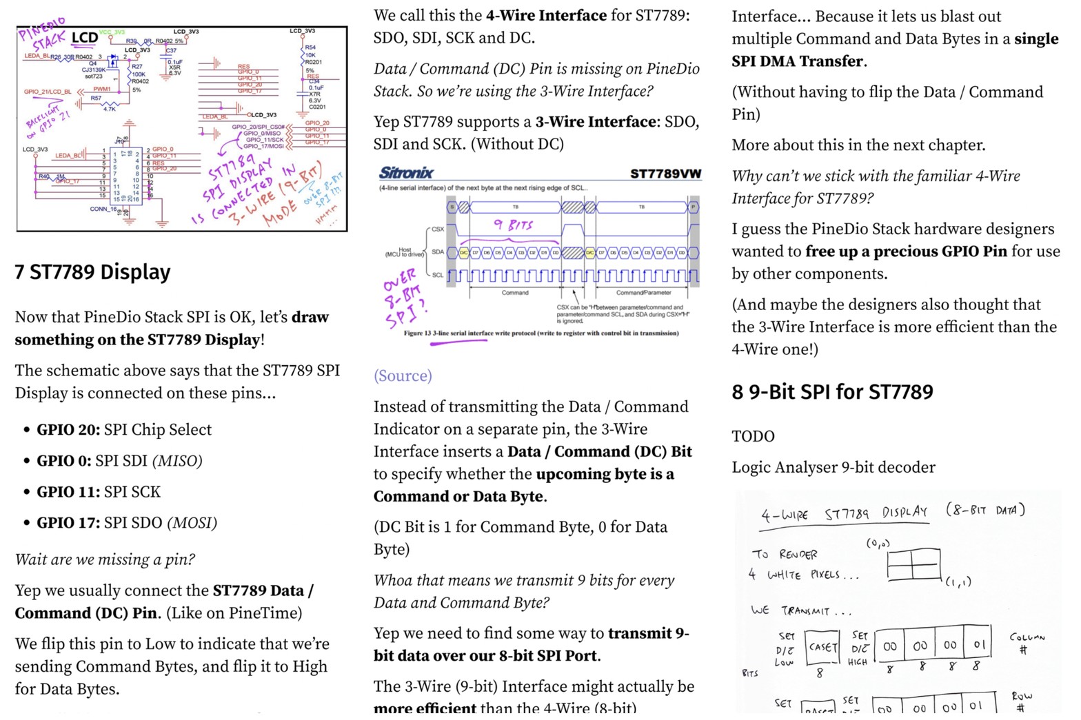
#PineDio Stack uses the 3-Wire Interface for #ST7789 ... Instead of the familiar 4-Wire Interface
https://lupyuen.github.io/articles/pinedio?11#st7789-display
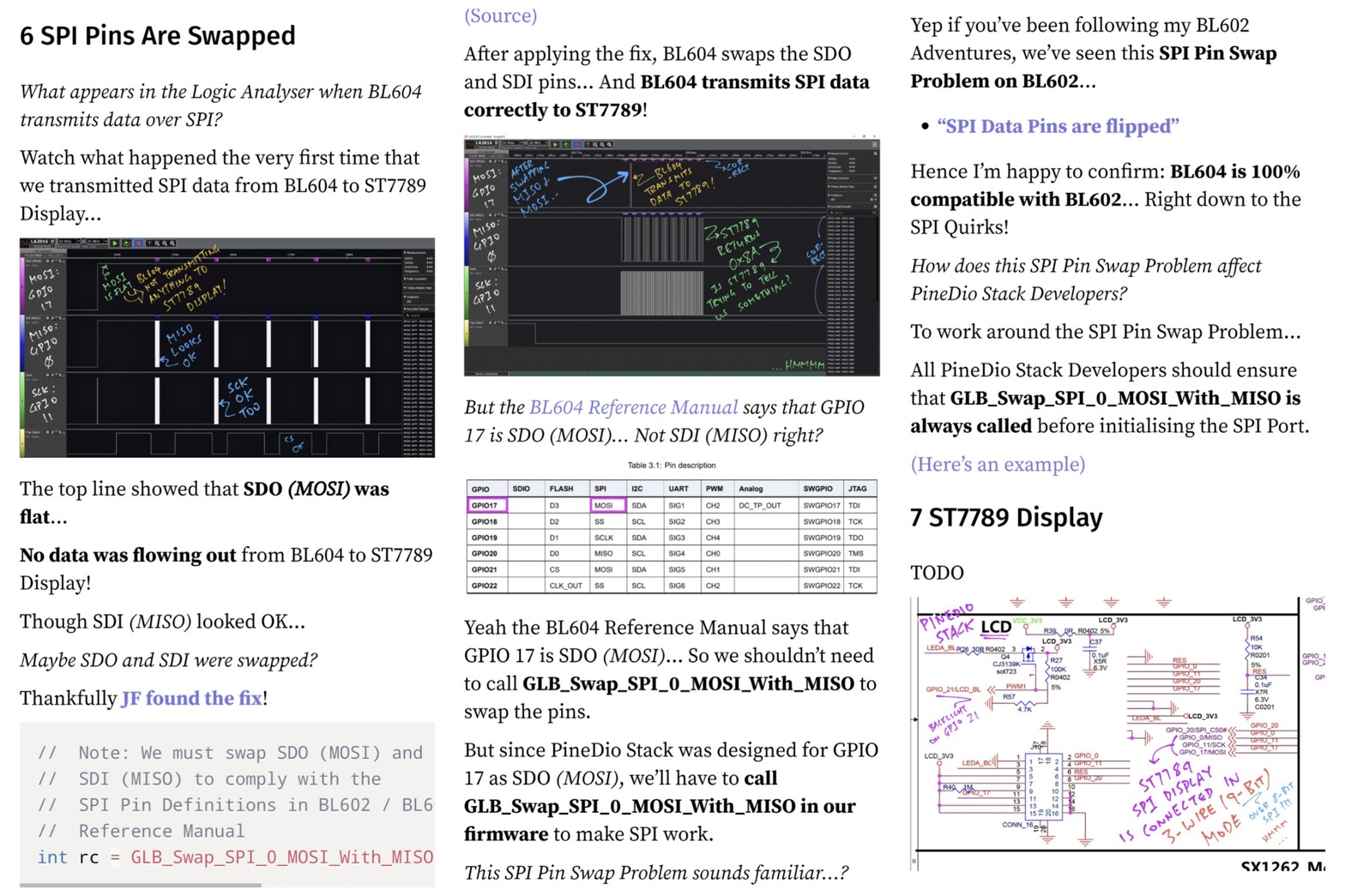
#BL604 SPI Pins are Swapped! 🙄 Here's the workaround for #PineDio Stack
https://lupyuen.github.io/articles/pinedio?10#spi-pins-are-swapped
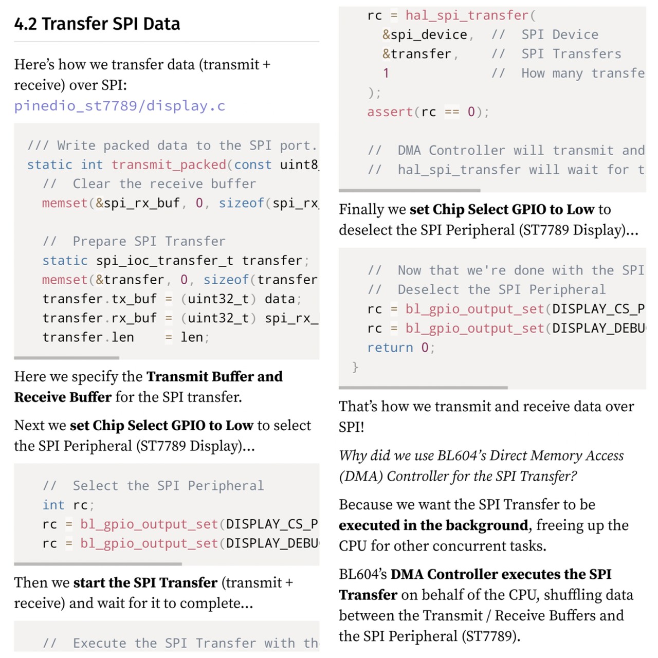
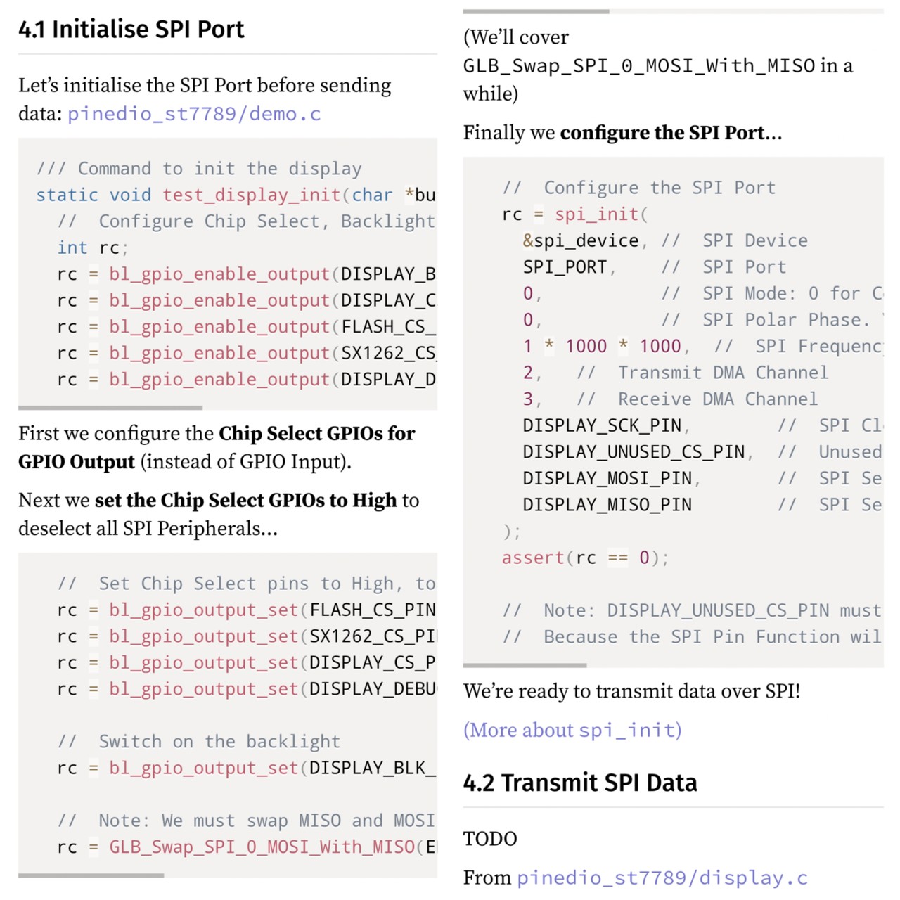
How we init the #PineDio Stack #BL604 SPI Port
https://lupyuen.github.io/articles/pinedio?7#initialise-spi-port
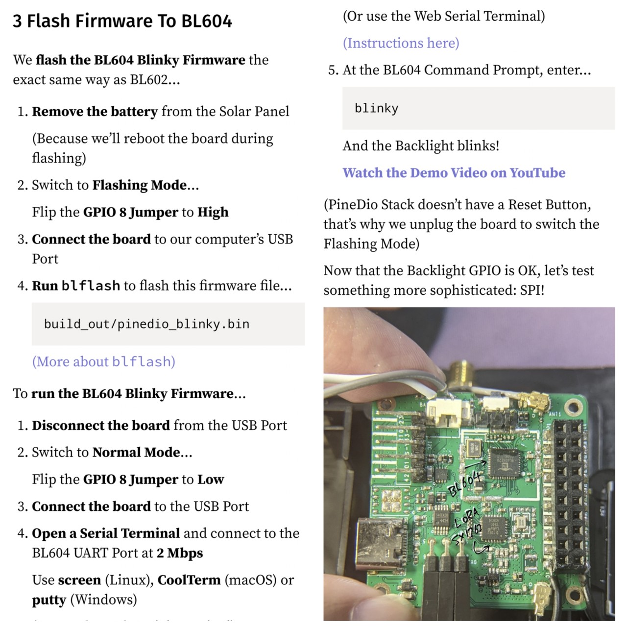
Flashing Firmware to #PineDio Stack #BL604 ... With the same tools as BL602!
https://lupyuen.github.io/articles/pinedio?5#flash-firmware-to-bl604
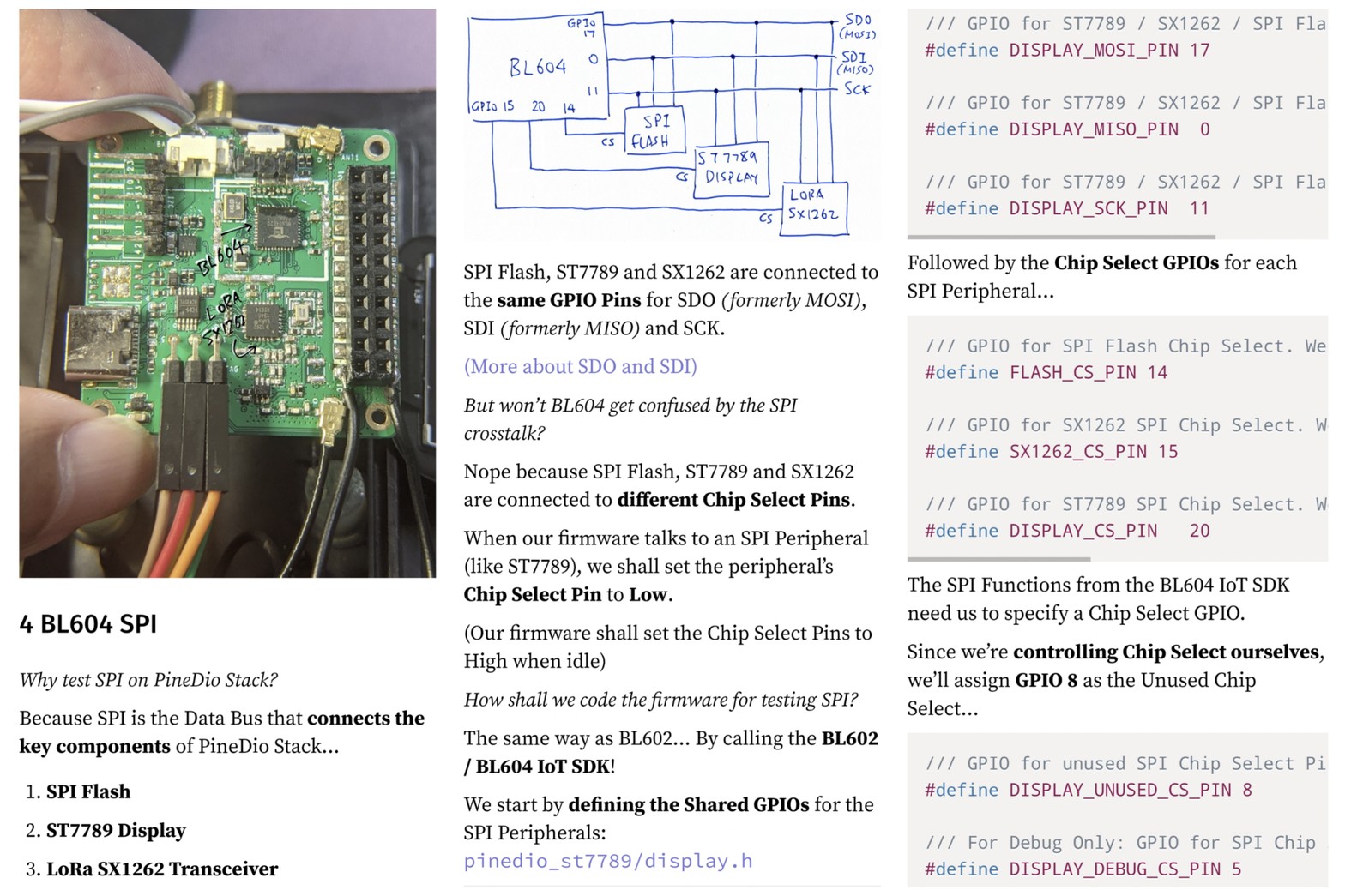
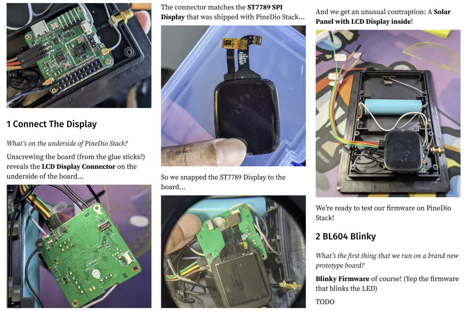
Connecting #PineDio Stack BL604 @PINE64 ... To a super-familiar ST7789 SPI Display
https://lupyuen.github.io/articles/pinedio?3#connect-the-display
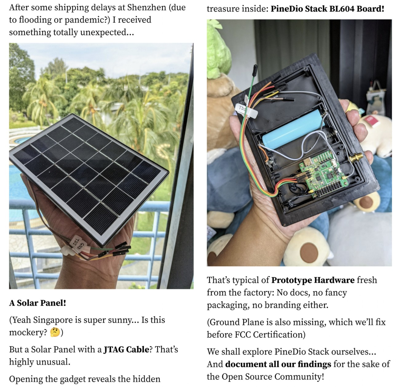
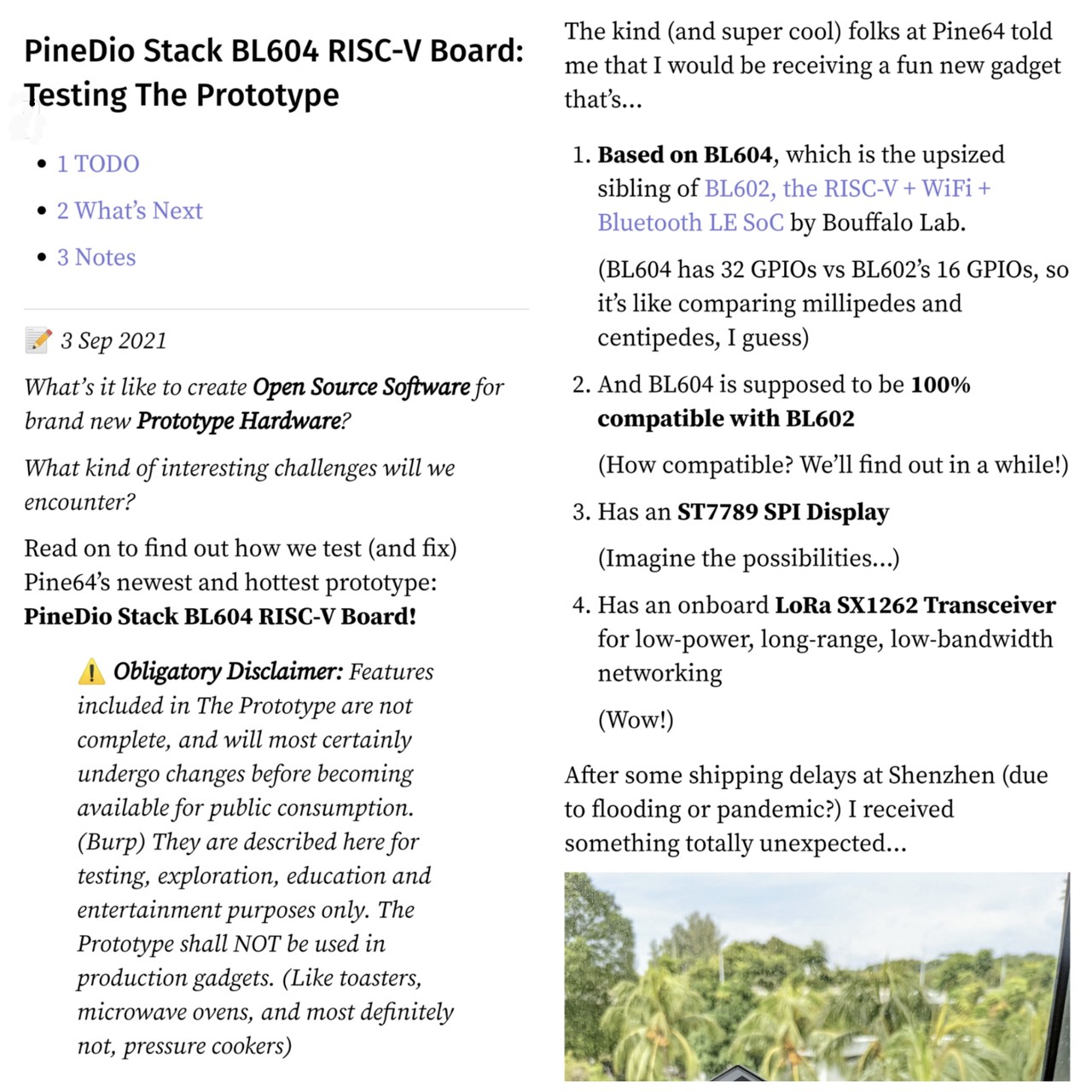
What's it like to create #OpenSource software for brand new Prototype Hardware ... Like #PineDio Stack BL604? All shall be explained in this article
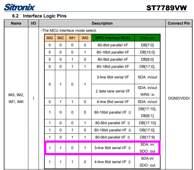
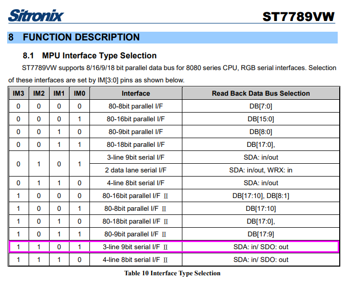
Since our #ST7789 Display doesn't respond to GFX Library 9-Bit Banging ... Maybe our display isn't hardwired for 3-Wire 9-Bit mode? Let's verify IM0 to 3 with the display maker
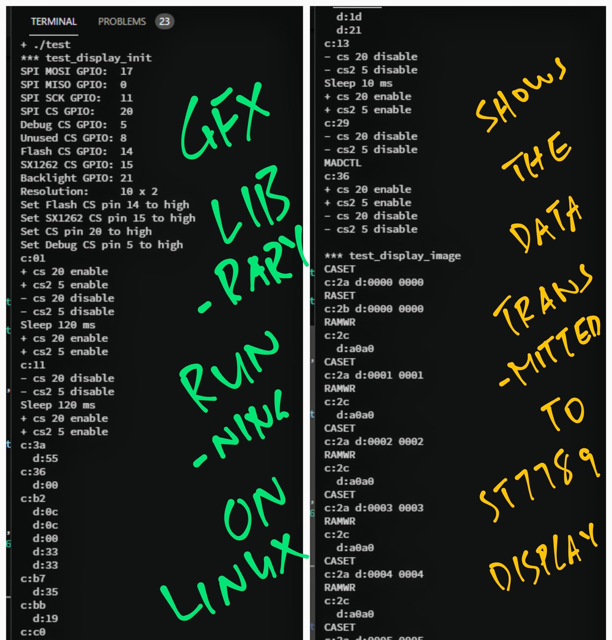
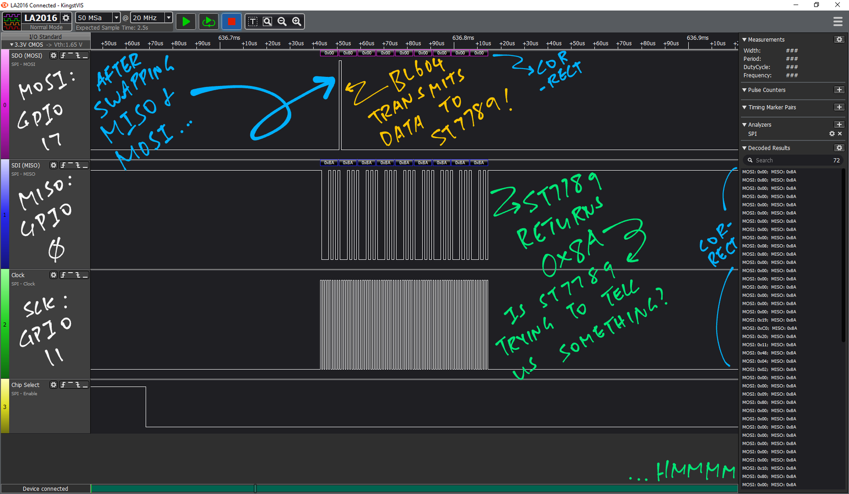
We run the GFX Library on Linux ... To see the data that will be transmitted to #ST7789 Display
https://github.com/lupyuen/bl_iot_sdk/blob/3wire/customer_app/pinedio_st7789_bitbang/test/test.c
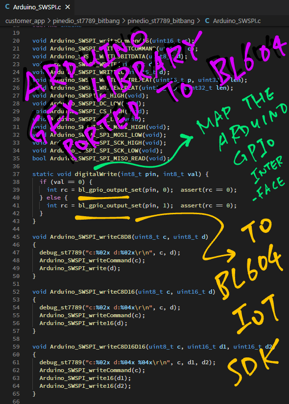
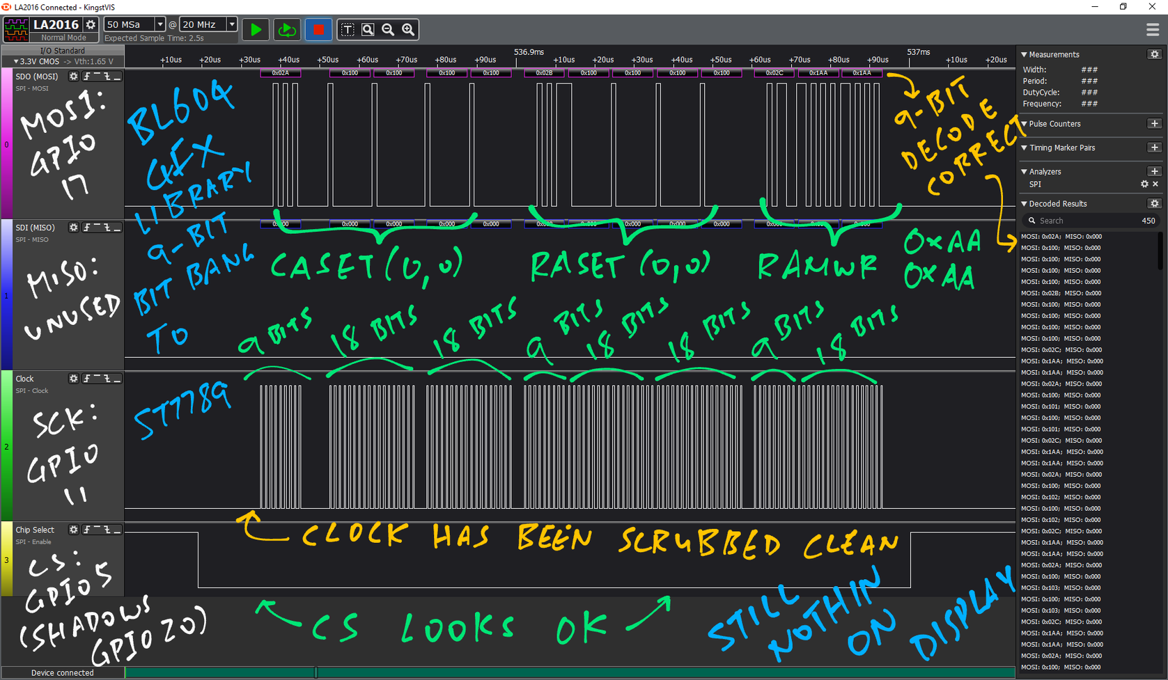
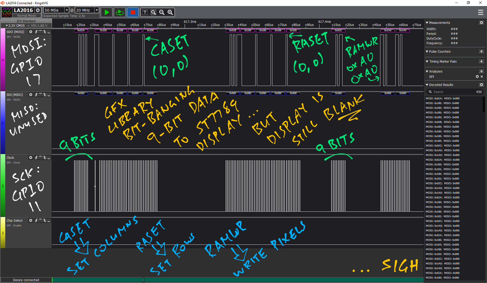
Let's port moononournation's awesome 9-bit-banging GFX Library to #BL604 ... And compare the SPI Output with a Logic Analyser
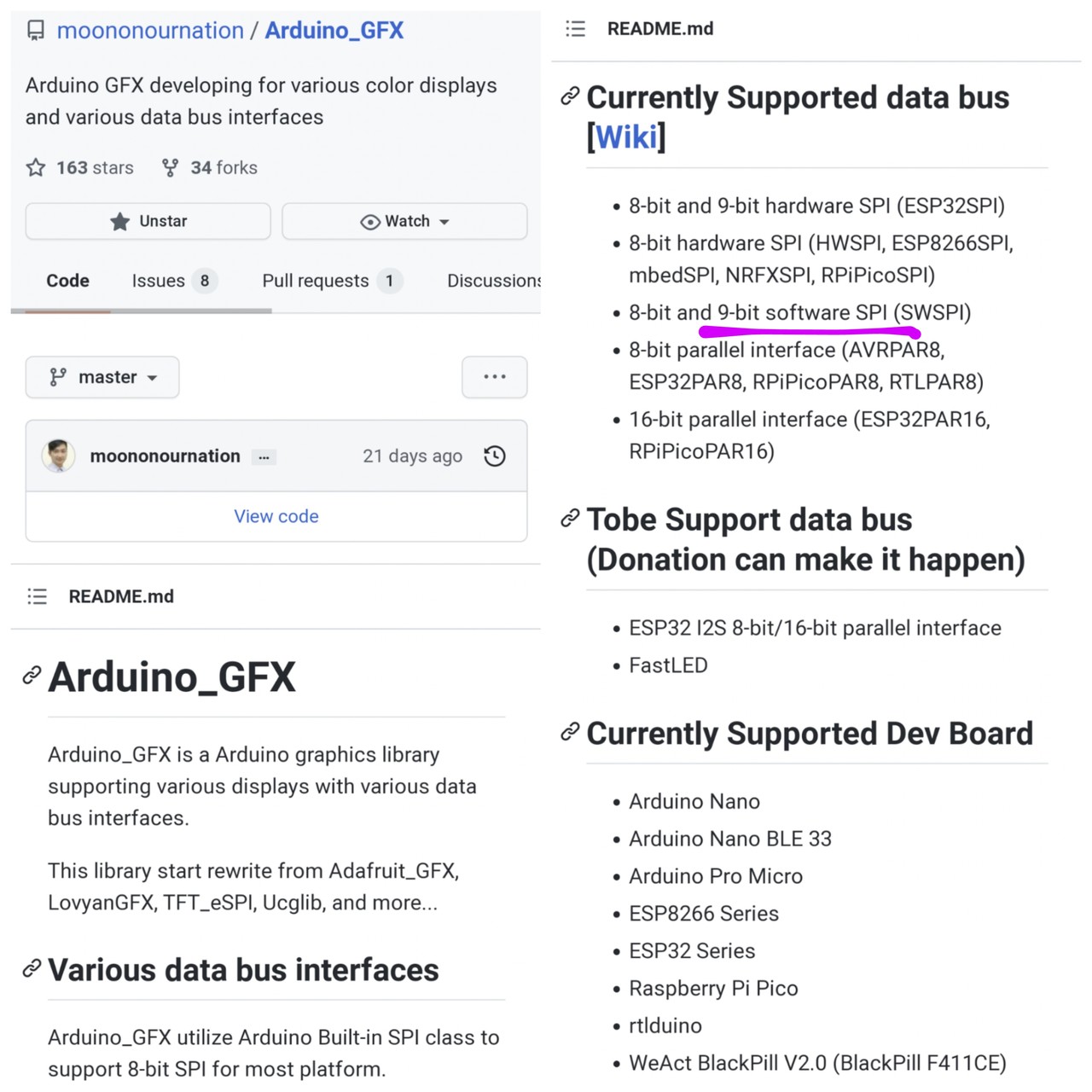
Need to verify that our #ST7789 Display is hardwired for "3-line 9bit serial I/F Ⅱ" mode: IM0 = 1, IM1 = 0, IM2 = 1, IM3 = 1 🤔
Yep MISO and MOSI are now swapped! This matches the SPI Pin Definitions in #BL604 Reference Manual ... So from now on we'll always call GLB_Swap_SPI_0_MOSI_With_MISO
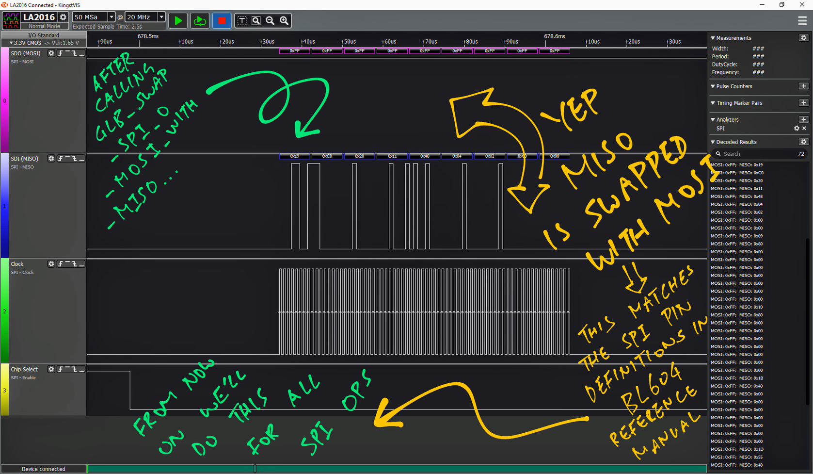
- Pronouns/Gender/Sexuality
- He/Him/They, Bisexual/Asexual 🇸🇬
- Date of Birth
- 1969
- Articles
- https://lupyuen.org
IoT Techie and Educator / Apache NuttX PMC
Joined Jan 2020
