

@niconiconi What's that? I'm confused by the thing-in-the-middle that has no connection to the coils around (and the two out of three pairs of coils that don't have any wires bonded to them).
@robryk@qoto.org Read the image description and you'll see it's the Linear Technology LTZ1000 ultra-stable Buried Zener voltage reference. This chip uses on-die heater coils to keep the diode at constant temperature (indeed, two of the coils appear to be unused design spare). Invented in the 1980s, it's a legendary chip in the history of semiconductor engineering, and still one of the best voltage references ever made, suitable for use in 8.5-digit voltmeters.
@niconiconi Ah, silly me for not noticing it. Thanks.
Huh, the way one should use it is somewhat funny (with the second identical transistor being used as a temperature sensor and the external heater controller).
Do you know what are the blemishes on pads with no wires? They seem to me like a wire was bonded and debonded there, but I don't see why that would be part of the production process (esp. given that the other two rings are narrower and shorter, so are unlikely to be viable substitutes for this one at production time).
@robryk@qoto.org Removed bounding wires are pretty common in these photographs. It's often difficult to extract the chip without touching the wires.
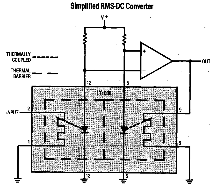
Also another fun fact, LTZ1000's technology came from another legendary LT chip - LT1088 RMS-to-DC converter, this is where the unused heaters were used from. LT1088 measures True RMS voltage by AC-DC thermal conversion. The input AC power is dissipated into an on-chip resistor, and you heat another on-chip resistor using DC power until both reach the same temperature, this is the very definition of RMS voltage. It's still the holy grail in metrology labs, and also standard for RF/microwave power measurements. But as far as I know, the LT1088 was the only attempt to do this in an off-the-shelf chip. Too bad it was never a commercial success and went out of production.
Ah, so those other resistors _were_ bonded to something for some purpose.
Was there some specific trick to avoid output oscillations in that method, or was that "just" a matter of tuning time constants of some very low pass filters on the opamp?
https://www.analog.com/media/en/technical-documentation/application-notes/an22.pdf shows a corresponding detailed circuit diagram.
D'oh; I didn't realize that _inputs_ to the opamp are prefiltered in the way you've described. Thanks.
