

DaveTLV @Surasanji@qoto.org
Account has been Depreciated. Thanks for all the fun, QOTO!
Joined Aug 2018
DaveTLV
boosted

@Surasanji Yup. It's a minimalist set up because I want to keep it as clean as I can, but I wanted to use the elements to give it some texture.
DaveTLV
boosted
Ok, made some updates to the previous mock that I think I like enough to build.
Friendly reminder that DARTZ vehicles once offered seats upholstered with the foreskin leather of mink whales.
DaveTLV
boosted

@Surasanji For any kind of RF really, but HAM radio too.
DaveTLV
boosted
Finally completed the 6th and final directional Coupler utilizing all the tricks I learned from the series. She is beautiful isn't she.
Wanted: Butler
Role ideal for enthusiastic animal who doesn't mind wearing clothes.
DaveTLV
boosted
Half of the final prototype for the directional Coupler complete. Isn't she pretty!
Cat Update:
My cat is still fantastic and I love her more everyday.
This has been your cat update.
DaveTLV
boosted
@Surasanji Custom blog software I'm working on https://code.playvicio.us/Are0h/Fipamo
DaveTLV
boosted
DaveTLV
boosted

I'm a very dancy person, and it makes me glad that my office is so secluded and open because I can just get up and dance to a good song sometimes!!!
DaveTLV
boosted
@Surasanji While it does have a shield, that would be true of anything carrying an RF signal really. But yes in this situation the outside of the boxes you saw do act as shields.
But aside from that it is not a "shield" just happens to use one. The shield isnt too important for the operation other than to make the output a bit cleaner. It actually works more like a transformer.
There are many ways to build a directional coupler. In my case I'm using a circuit called a "Tandem Match" circuit. Its basically two transformers. One on the main line carrying the high power (up to 1500W in this case). That transformer is a 1:20 ration with the "1" just being the high power line running straight through the middle of the toroid, and the toroid having the 20 turns around it. this is matched on the other side with a "mirror image" between the two coupled ports (the ones where a smalls sample of the forward and reverse waves come out). In this case however the transform is reversed from the direction it was in on the main line. The two transformers balance each other such that the main power line doesn't get effected very much so the DC wont disrupt the existing signal in any meaningful way (though it will loose a tiny bit of power). The two transformers also serve to "sense' voltage and current seperately.
This then spits the waves out the two smaller ports in a rather clean way.
Now WRT shielding there is some special shielding going on here that you wont usually see. It doesnt result in the actual function but as i said just makes the signal cleaner. Youll notice in all of my designs the thick wires running through the center of each toroid has a wire mesh around the outside and is grounded ONLY on one end. In addition in the copper case based designs there is an additional vertical wall separates the two toroids, this is another level of shielding.
Also a sort of form of shielding is the fact that the two toroids are positions at 90 degree angles to each other. This eliminates some parasitic inductance (not capacitance) and prevents the two transformers themselves to affect each other as inductors would (instead of as capacitors).
It would work fine with none of this shielding it would just be less predictable (it would respond to slight changes in frequencies by slightly changing its sensitivity a bit). That because when you have two wires running near each other they accidentally create a very low value capacitor between them. This is called "parasitic capacitance" and is undesirable and causes the issues. all this extra shielding i just mentions eliminates a lot of parasitic capacitance and gives a really clean output.
Thats why i didnt go to the same lengths of shielding on the silver boxes. They were prototypes so not worth the effort. Its only on attempts at final designs (the copper boxes) I add the extra level of shielding to create a final product.
DaveTLV
boosted
@Surasanji A directional coupler itself seperates out electrical waves traveling in opposite directions down a wire into the forward and reverse components so they can be analyzed. This alone is useful for things beyond just radio.
the purpose for me however is as a component to my ROES meter I've posted before. You seperate out the waves going to your antenna from your radio, and those moving from the antenna to the radio (the ones reflected back by the antenna). By comparing these two waves using specialized chips in the ROES it is possible to analyze the efficiency of your antenna as well as know what you have to do to improve your antenna system (how to get your antenna to transmit more power rather than to waste it).
DaveTLV
boosted
Punisher season 2 drops tomorrow, so that means I have to binge season 1 today, right?
DaveTLV
boosted
Started the final draft of the directional Coupler. Building in extra levels of shielding and a 20:1 winding ratio. I'm stoked to finally have the design locked down
#RF #EE #Electronics #Engineering #Science #ElectricalEngineering #RFEngineering #HAM #HamRadio
DaveTLV
boosted
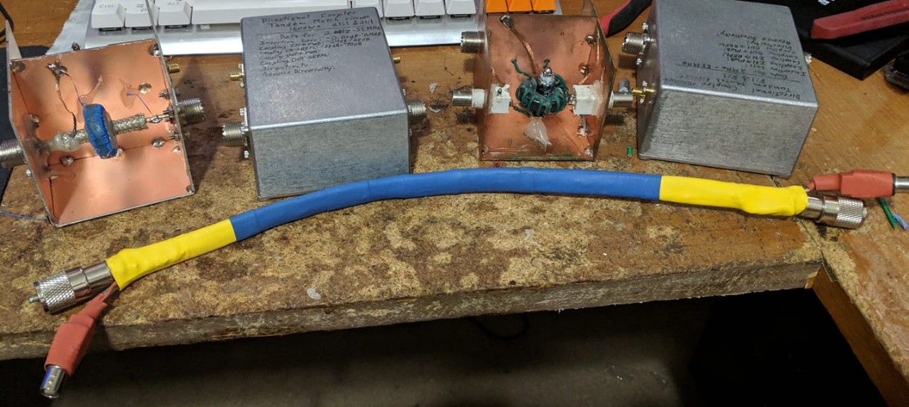
Over the past few days I built 5 different Directional couplers. Each one uses either a new design even tierly or a new winding ratio. After all the testing I've finally figured out the ideal design for the frequency range I'm targeting. Time to build the final prototype.
#RF #EE #Electronics #Engineering #Science #ElectricalEngineering #RFEngineering #HAM #HamRadio
DaveTLV
boosted
Oh and hey.
Good morning, lovely people. You look great today. Go forth and flourish on this day of Thurs.
DaveTLV
boosted

I finally did it. It's a 0.0.1 but it's a _release_. Just bit the bullet and did it, lol.

Account has been Depreciated. Thanks for all the fun, QOTO!
Joined Aug 2018
