

🎓 Doc Freemo  🇳🇱
@freemo@qoto.org
🇳🇱
@freemo@qoto.org
- UFoI Member
- http://UFoI.org/u/freemo/
- Website
- http://JeffreyFreeman.me
- Gitlab
- https://git.qoto.org/freemo
Admin
Jeffrey Phillips Freeman
Innovator & Entrepreneur in Machine Learning, Evolutionary Computing & Big Data. Avid SCUBA diver, Open-source developer, HAM radio operator, astrophotographer, and anything nerdy.
Born and raised in Philadelphia, PA, USA, currently living in Utrecht, Netherlands, USA, and Thailand. Was also living in Israel, but left.
Pronouns: Sir / Mister
(Above pronouns are not intended to mock, i will respect any persons pronouns and only wish pronouns to show respect be used with me as well. These are called neopronouns, see an example of the word "frog" used as a neopronoun here: http://tinyurl.com/44hhej89 )
A proud member of the Penobscot Native American tribe, as well as a Mayflower passenger descendant. I sometimes post about my genealogical history.
My stance on various issues:
Education: Free to PhD, tax paid
Abortion: Protected, tax paid, limited time-frame
Welfare: Yes, no one should starve
UBI: No, use welfare
Racism: is real
Guns: Shall not be infringed
LGBT+/minorities: Support
Pronouns: Will respect
Trump: Moron, evil
Biden: Senile, racist
Police: ACAB
Drugs: Fully legal, no prescriptions needed
GPG/PGP Fingerprint: 8B23 64CD 2403 6DCB 7531 01D0 052D DA8E 0506 CBCE
Joined Jul 2018
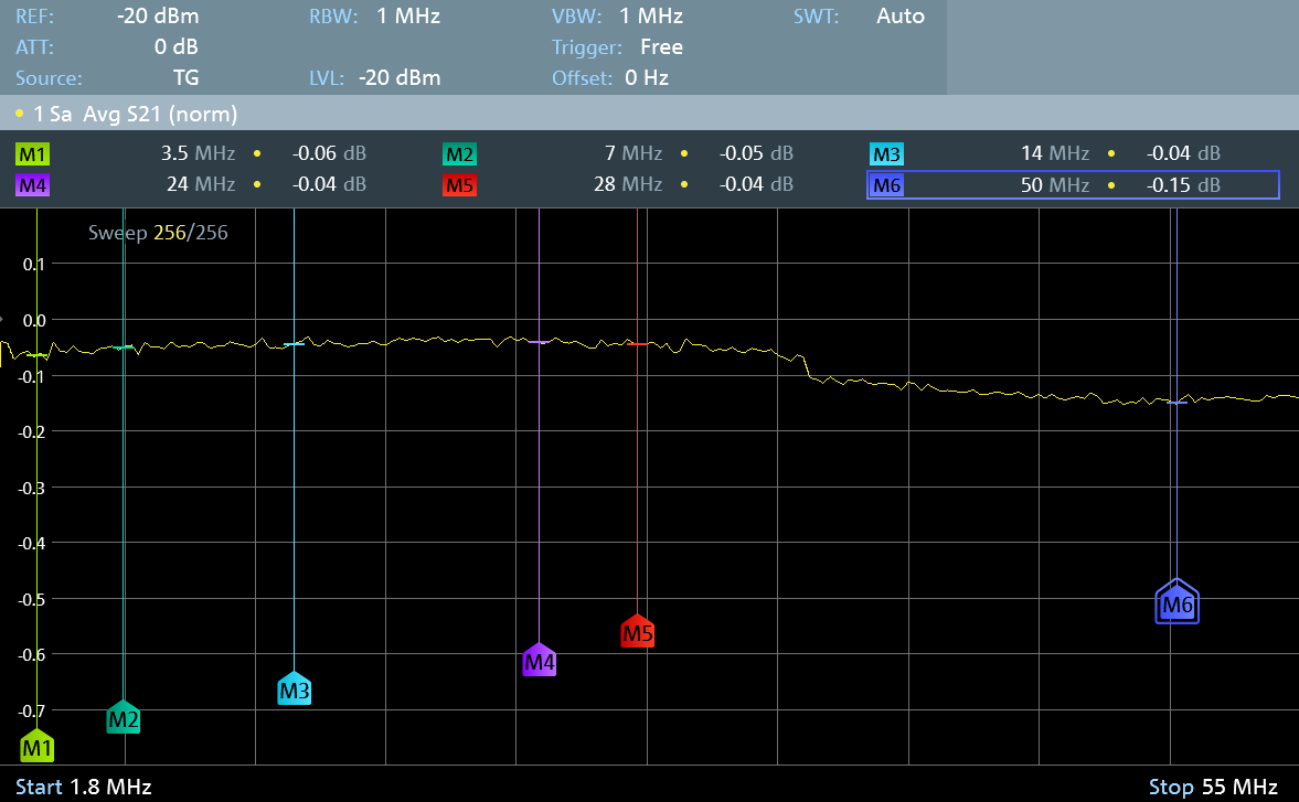
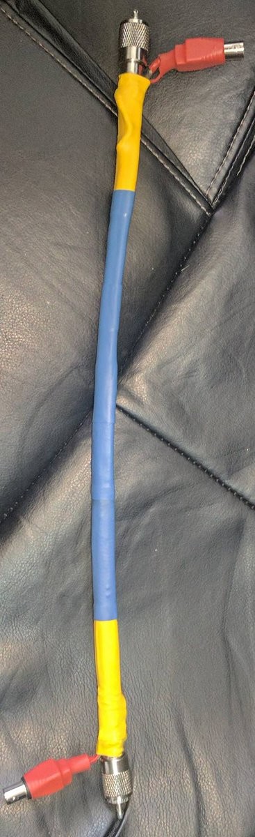
Woot, just tested the Insertion Loss on the directional Coupler I built. It has an amazing -0.05dB IL on most frequencies except 50MHz where it is still only -0.15dB!
#RF #EE #Electronics #Engineering #Science #ElectricalEngineering #RFEngineering #HAM #HamRadio
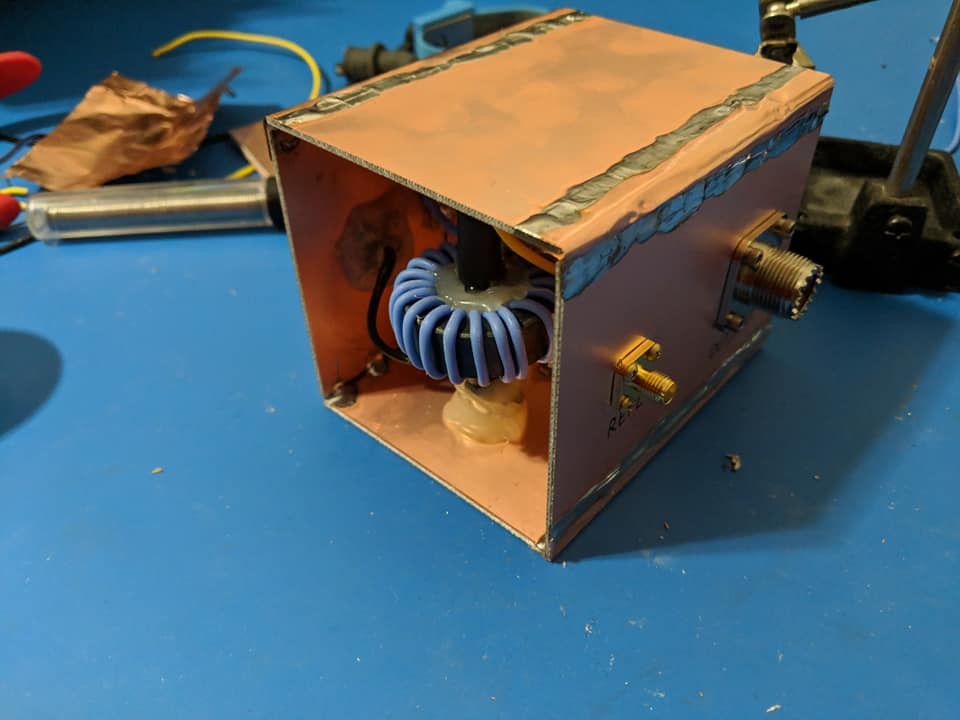
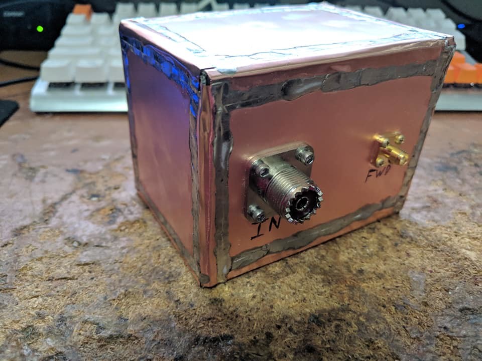
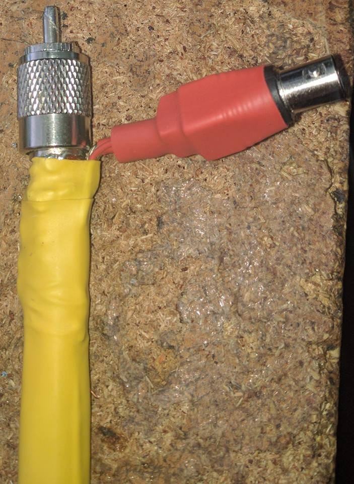
I finally had the nerve to seal her up. Next I am going to clean up the outside and put a coat of laquer on her before she begins to get a patina.
#RF #EE #Electronics #Engineering #Science #ElectricalEngineering #RFEngineering #HAM #HamRadio
Started the final draft of the directional Coupler. Building in extra levels of shielding and a 20:1 winding ratio. I'm stoked to finally have the design locked down
#RF #EE #Electronics #Engineering #Science #ElectricalEngineering #RFEngineering #HAM #HamRadio
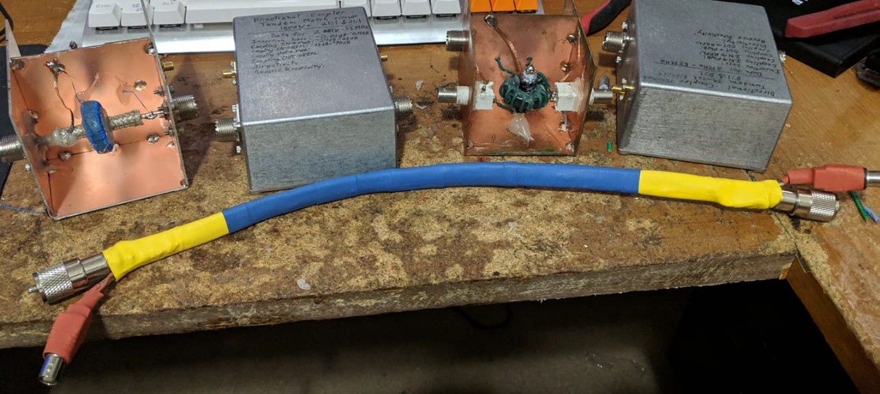
Over the past few days I built 5 different Directional couplers. Each one uses either a new design even tierly or a new winding ratio. After all the testing I've finally figured out the ideal design for the frequency range I'm targeting. Time to build the final prototype.
#RF #EE #Electronics #Engineering #Science #ElectricalEngineering #RFEngineering #HAM #HamRadio
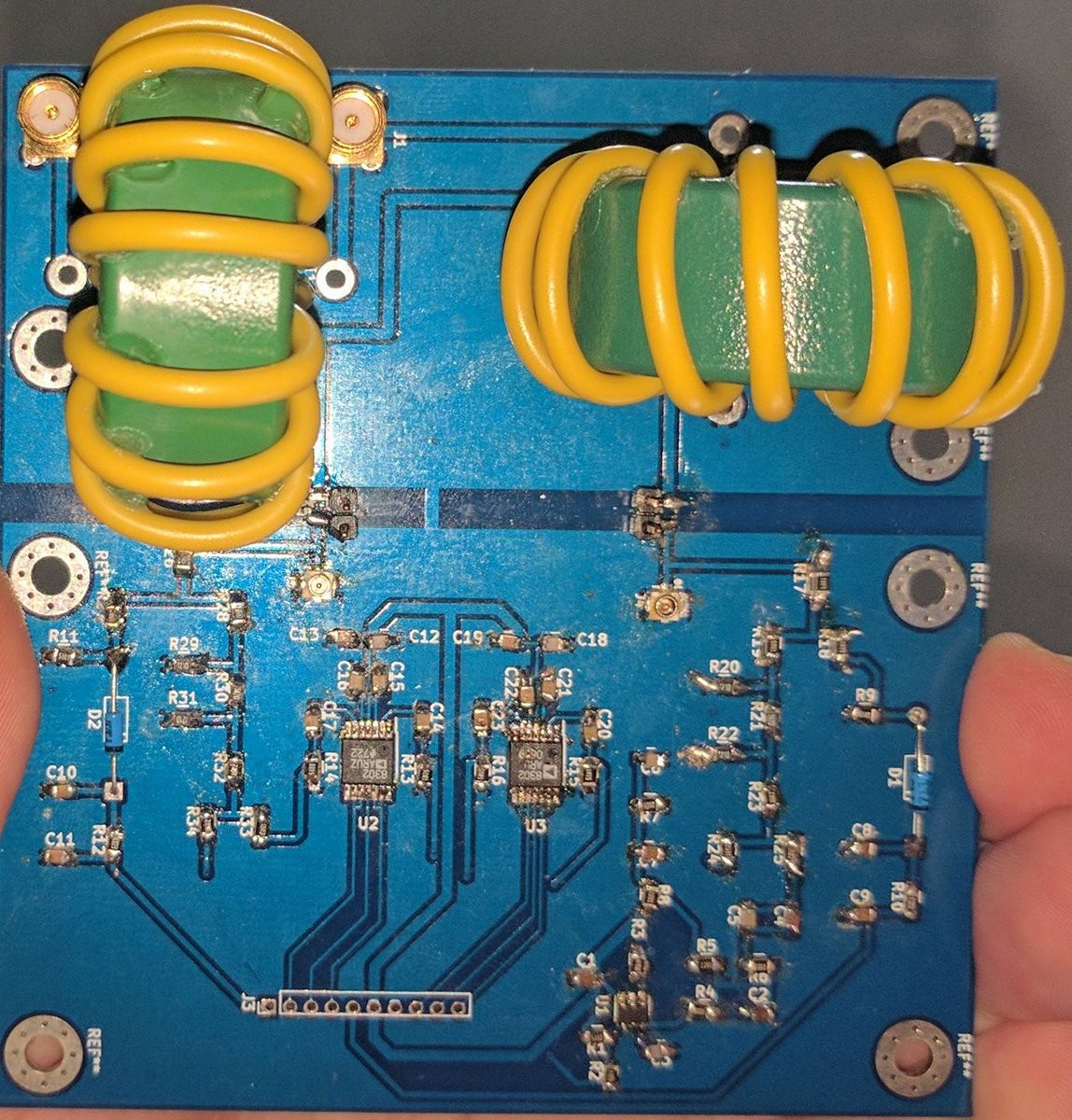
It took me 3 hours but I rolled two perfect 126 turn Toroid inductors. These will be two halves of the two transformers in a Tandem Match Circuit (Directional Coupler). Should have infinitesimal insertion loss
#RF #EE #Electronics #Engineering #Science #ElectricalEngineering #RFEngineering #HAM #HamRadio
Decided to build another tandem match circuit based directional Coupler. This time I used a 21:1 winding ratio instead of the last one at 8:1.
It seems to have reduced unwanted coupling at lower frequencies. But more important it decreased insertion loss from about 1.15dB to only 0.03dB at 2 MHz and 0.4dB around 50MHz.
I think I prefer this particular winding ratio for my design.
#RF #EE #Electronics #Engineering #Science #ElectricalEngineering #RFEngineering #HAM #HamRadio
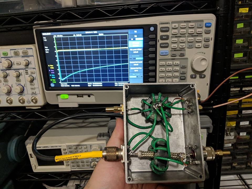
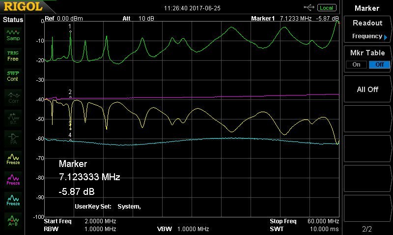
So my Directional Coupler performed fairly well. Here is the output from my spectrum analyzer. Basically one trace is for the forward port when the antenna is matched, the other is when the antenna is an open circuit. Then the other two traces are the same condition on the reflected port.
As you can see all the powers show a nice flat -20db coupling. Only exception is the one cyan trace that shows the reflected port when the antenna is matched. Since there are no reflections as expected the response is much less. It is also not linear which is to be expected.
Pretty similar results to my last attempt. Though going with fewer windings this time (8 instead of 12) seems to have results in a slight stronger coupling (-20 dBM rather than the -23 dBM I got before).
All in all I'd say its a success.
#RF #EE #Electronics #Engineering #Science #ElectricalEngineering #RFEngineering #HAM #HamRadio
Woot! Just finished my high power directional Coupler. She works perfectly. A day well spent.
#RF #EE #Electronics #Engineering #Science #ElectricalEngineering #RFEngineering #HAM #HamRadio
A sneak peek at the Schematic for Version 2.0 of the ROES meter (A SWR meter with VNA capability).
#AmateurRadio #electronics #Radio #ham #Engineering #RF #HamRadio #EE #Electronics #Arduino #AVR
Was running my new project in demo mode where it just continually increases the phase and magnitude of a load's complex value then plots it on a Smith chart. I was pleasantly surprised when I noticed it produced a Celtic knot pattern.
#HAM #Engineering #RF #HamRadio #RF #EE #Electronics #Arduino #AVR
A sneak peek at the first draft for the new UI in V2 of my ROES meter, an advanced SWR meter with VNA capabilities.
I still need to cleanup the location of the axis labels, and I want move around a few other elements. But it is coming along very nicely.
I can stare at this smith chart being generated all day long :)
#HAM #Engineering #RF #HamRadio #RF #EE #Electronics #Arduino #AVR
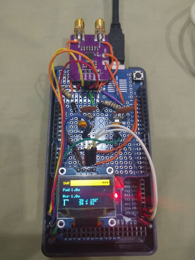
Beginning work on a version 2 of my SWR+VNA meter (ROES). Using a new much larger full color touch display. I have some debugging to do but it partly works with existing code, so yay.
I will be completely redoing the UI to add colors and various graphical representations such a Smith Chart showing the complex Reflection Coefficient (Complex SWR).
I will also be adding an extremely accurate frequency counter up to 2 GHz to improve the accuracy of the device and include a frequency readout on the display.
#HAM #Engineering #RF #HamRadio #RF #EE #Electronics #Arduino #AVR
A picture of an early prototype for my ROES SWR meter and VNC. I later had to completely redesign the hardware for version 1.0, but the UI is still pretty similar.
This week I hope to add a frequency counter to the design and work towards a v2.
PS: See my pinned post to see v1 in action along with the analog board. The post also includes the v1 Schematic
#EE #Electronics #Ham #HamRadio #RF #SCience #Engineering #ElectricalEngineering #ROES #SWR
Ok that was crazy cool, techno using various homemade robots: https://youtu.be/wHrCkyoe72U
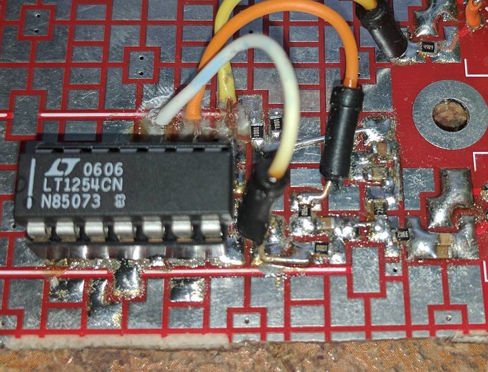
A wide-band phase shift circuit I just finished building. She ain't the prettiest, but she works!
A new(ish) blog entry! This one explains how to do nodal analysis on an electronic circuit. I wrote it a few years ago but just ported it to my blog:
http://jeffreyfreeman.me/nodal-analysis-tutorial/
#Electronics #ElectricalEngineering #Math #Mathematics #AnalogCircuits #CircuitAnalysis #Circuit #Circuits
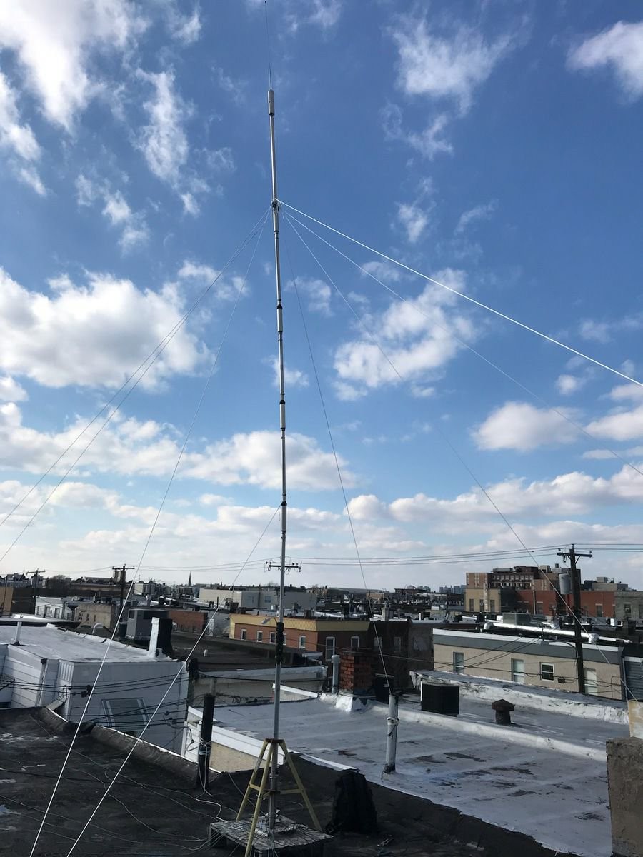
An analysis of my 27' vertical antenna (6BTV). The green line shows the antenna's resonance. The peaks are the frequencies the antenna is best suited to transmit at. 0dB on the image is roughly a SWR of 1; -20dB is approx infinite SWR.
A close up of the SWR meter's analog board.
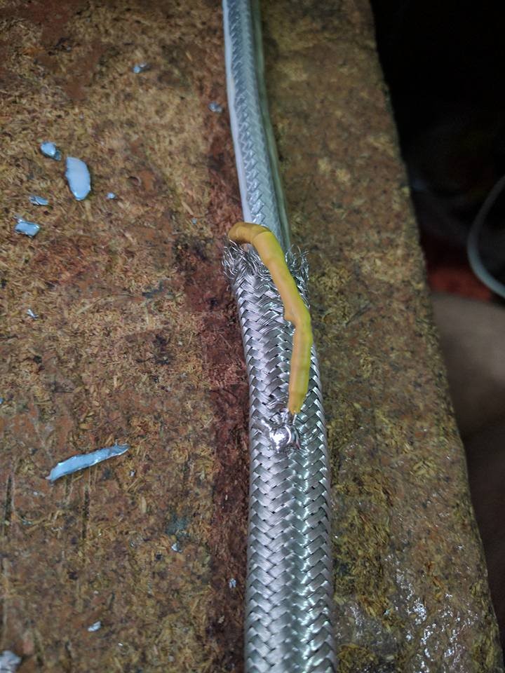
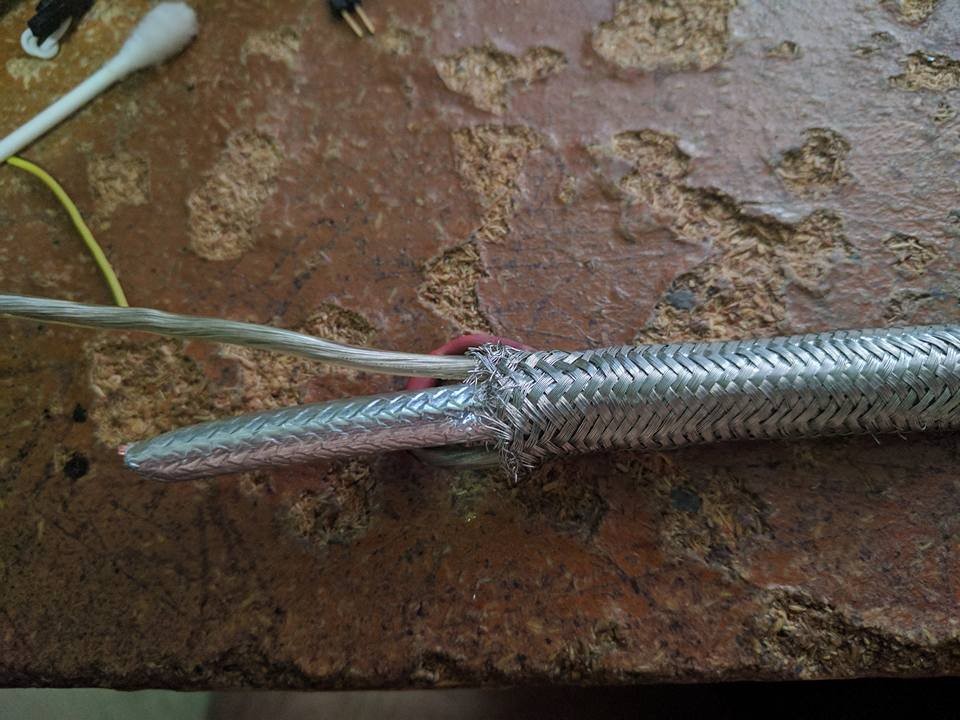
A quick build of a cheap and easy Directional coupler using the coupled transmission line approach. You cant see it in the images but there are two 50 ohm terminating resistors on the end of each coupling.
An Advanced SWR meter I built about a month ago. It calculates phase shift so can compute a complex impedance and complex SWR, something most meters cant do. Schematics included.
https://github.com/Syncleus/roes
https://github.com/Syncleus/roes-hardware
- UFoI Member
- http://UFoI.org/u/freemo/
- Website
- http://JeffreyFreeman.me
- Gitlab
- https://git.qoto.org/freemo
Admin
Jeffrey Phillips Freeman
Innovator & Entrepreneur in Machine Learning, Evolutionary Computing & Big Data. Avid SCUBA diver, Open-source developer, HAM radio operator, astrophotographer, and anything nerdy.
Born and raised in Philadelphia, PA, USA, currently living in Utrecht, Netherlands, USA, and Thailand. Was also living in Israel, but left.
Pronouns: Sir / Mister
(Above pronouns are not intended to mock, i will respect any persons pronouns and only wish pronouns to show respect be used with me as well. These are called neopronouns, see an example of the word "frog" used as a neopronoun here: http://tinyurl.com/44hhej89 )
A proud member of the Penobscot Native American tribe, as well as a Mayflower passenger descendant. I sometimes post about my genealogical history.
My stance on various issues:
Education: Free to PhD, tax paid
Abortion: Protected, tax paid, limited time-frame
Welfare: Yes, no one should starve
UBI: No, use welfare
Racism: is real
Guns: Shall not be infringed
LGBT+/minorities: Support
Pronouns: Will respect
Trump: Moron, evil
Biden: Senile, racist
Police: ACAB
Drugs: Fully legal, no prescriptions needed
GPG/PGP Fingerprint: 8B23 64CD 2403 6DCB 7531 01D0 052D DA8E 0506 CBCE
Joined Jul 2018
