

🎓 Doc Freemo  🇳🇱
@freemo@qoto.org
🇳🇱
@freemo@qoto.org
- UFoI Member
- http://UFoI.org/u/freemo/
- Website
- http://JeffreyFreeman.me
- Gitlab
- https://git.qoto.org/freemo
Admin
Jeffrey Phillips Freeman
Innovator & Entrepreneur in Machine Learning, Evolutionary Computing & Big Data. Avid SCUBA diver, Open-source developer, HAM radio operator, astrophotographer, and anything nerdy.
Born and raised in Philadelphia, PA, USA, currently living in Utrecht, Netherlands, USA, and Thailand. Was also living in Israel, but left.
Pronouns: Sir / Mister
(Above pronouns are not intended to mock, i will respect any persons pronouns and only wish pronouns to show respect be used with me as well. These are called neopronouns, see an example of the word "frog" used as a neopronoun here: http://tinyurl.com/44hhej89 )
A proud member of the Penobscot Native American tribe, as well as a Mayflower passenger descendant. I sometimes post about my genealogical history.
My stance on various issues:
Education: Free to PhD, tax paid
Abortion: Protected, tax paid, limited time-frame
Welfare: Yes, no one should starve
UBI: No, use welfare
Racism: is real
Guns: Shall not be infringed
LGBT+/minorities: Support
Pronouns: Will respect
Trump: Moron, evil
Biden: Senile, racist
Police: ACAB
Drugs: Fully legal, no prescriptions needed
GPG/PGP Fingerprint: 8B23 64CD 2403 6DCB 7531 01D0 052D DA8E 0506 CBCE
Joined Jul 2018
Help! From anyone interested in English, Physics, Math, or Science.
I have written a rather massive article in the hopes of teaching people with mid-level knowledge in electronics about the idea of Duals in mathematics, how that applies to circuits and the various types of circuit duals that exist
I also include a great deal of detail in the end about one very obscure and rarely studied circuit dual called the magnetic circuit dual, it is a circuit, like a magnetic circuit, but instead of current being the flow of electrons, it is the flow of a magnetic field through wires made of iron instead of copper.
I even touch on briefly how one can extract energy from permanent magnets and other details most people arent very familiar with.
The problem is the article is massive and I really could use some eyes on it. Whether its just to try to help me catch english mistakes, or if your not that experienced perhaps tell me the parts that are confusing, as I would like this to be accessible to people who may not be scientists and only know entry level electronics or science. any feedback from anyone at any level would be highly appreciated.
Keep in mind I couldn't find many good sources laying out the equations for magnetic circuits very clearly so I had to derive a lot of the equations myself, though the concept is well established as fact and many peer-reviewed papers have been written on it. But bear in mind there may be minor errors in my math as well, so that too needs some criticism, though the math should be fairly close to correct.
Anyway any input from anyone would be much appreciated.
The draft of the article can be found on the beta site for my blog, here is a direct link:
http://beta.jeffreyfreeman.me/an-indepth-look-at-duals-and-their-circuits/
Similarly if you find any mistakes you can message me here, or you can leave a merge request on the repo for the article, here is the direct link to the markdown file in the source for my blog:
It is much prefered that if you have specific edits like english or math you do it as a pull request as it can be a huge pain for me to hunt down the specific part of the text you are referring to if you point out mistakes as replies here. However if your unwilling to do a merge request please still ping me here as I'd rather know than to just let it go unnoticed.
Anyone who helps I will add a thank you with your name and a link to your own site at the bottom of the article if you wish, this might help draw some traffic to your own site.
#Electronics #EE ##RF #HamRadio #AmateurRadio #Science #Physics #Math #Maths #Mathematics #English
I have been writing a blog article that is getting so big its a small text book at this point. Easily the biggest and more detailed blog article on a subject I have ever wrote.
The topic is Duals of Electrical circuits.
It takes me half the paper to even get to electronics, I start by trying to describe what a dual is in general terms, give simple mathematical examples, then go onto duals of systems of equations where I finally tie it into electrical circuits.
At that point I dive into a series of examples of different types of duals for electrical circuits, and then finally end with describing a magnetic circuit as a dual for an electric circuit, where the power sources become magnets, the copper wires are replaced with iron ones, electrical current is replaced with magnetic current (which is a propagating magnetic field), and then I explain each magnetic dual for each discrete component like capacitors, inductors, resistors, and transformers. Needless to say this thing gets really deep really fast.
If your interested in seeing the final result keep an eye out on my blog, should be released any day now.
http://jeffreyfreeman.me/an-indepth-look-at-duals-and-their-circuits/
#Electronics #EE ##RF #HamRadio #AmateurRadio #Science #Physics #Math #Maths #Mathematics
As you all know the earth is a giant magnet. As a giant magnet antarctica would be the north or south pole of that magnet?
So I just provided the answer to this Stackexchange question and I noticed something kinda cool and interesting in the final equation:
The equation, for those of you on a Latex capable instance is:
\( k \cdot \frac{N_p}{N_s} \cdot \sqrt{\frac{L_s}{L_p}} = R_\phi\)
In this case R, the flux linking ratio, must be a value between 0 and 1 and represents the percentage of flux that is mutual between two coupled inductors (a transformer).
Similarly k is Coefficient of Coupling, which is also a ratio between 0 and 1. It is a different measure of how well coupled two inductors are.
What I find interesting about the equation is that all the other variables can be anything from 0 to infinity, so at first glance you would think that it would be possible to have a scenario where either R or k are greater than 1. But in reality because the number of windings of the primary and secondary have a reciprocal relationship to that of the square root of the ratio of the inductances, in reality any real world values that you could plug in here would actually never be able to produce a contradiction.
If you look at the equation to calculate the inductance of an inductor based on its number of turns this becomes obvious. for simplicity if we assume the diameter if the inductor and the wire thickness are all the same then the relationship is basically the following:
\( L = N^2 \cdot C \)
Where L is the inductance, N is the number of turns, and C is some constant. So essentially the square of the number of turns of the inductor is linearly proportional to its inductance. Going back to the equation I was talking about this basically counters the sqrt function in the equation and it becomes obvious why any real world values would always satisfy the equation correctly.
#Electronics #ElectricalEngineering #EE #Math #Science #Physics #Maths #Mathematics
A fun article I just wrote explaining what the Reflection Coefficient is and how it can be used:
http://jeffreyfreeman.me/understanding-the-reflection-coefficient/
#Electronics #RF #Radio #Maths #Math #Mathematics #Physics #HamRadio #Ham #AmateurRadio
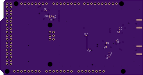
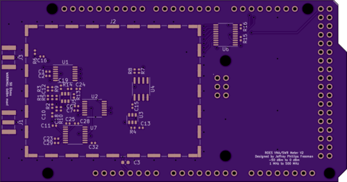
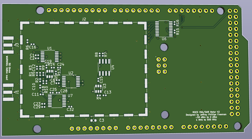
So for those of you following my #ROES project ("Ridiculously Over Engineered SWR Meter") which I've been active on the past few days I finally just sent the boards off to be printed for a prototype run. so V2.0 is officially released (though I may do a minor revision before printing up a large number of boards).
Attached are some screenshots of the final schematic and some renderings of what the boards will look like when its done. Its a 4 layer board though so many of the traces are internal.
You can find the files for this, which will be released as open-source, here:
https://git.qoto.org/roes/roes-hardware/
#Ham #HamRadio #Radio #RF #EE #Electronics #ElectricalEngineering #Science
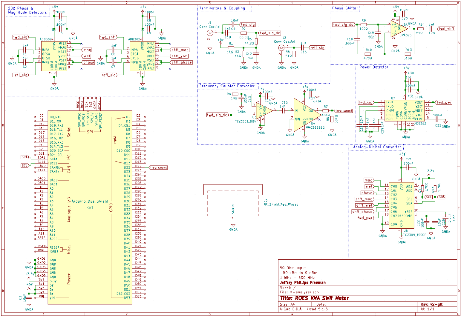
So I fixed a few more mistakes in the the V2 schematic for my "Ridiculously Over Engineered SWR Meter". Attached is the new schematic.
You can find the files for this, which will be released as open-source, here:
https://git.qoto.org/roes/roes-hardware/
#Ham #HamRadio #Radio #RF #EE #Electronics #ElectricalEngineering #Science #ROES
For those following along I have made some minor corrections to the V2 schematic for my "Ridiculously Over Engineered SWR Meter". Attached is the new schematic.
You can find the files for this, which will be released as open-source, here:
https://git.qoto.org/roes/roes-hardware/
#Ham #HamRadio #Radio #RF #EE #Electronics #ElectricalEngineering #Science #ROES
I think I may have finally finished the Version 2 Schematic of my "Ridiculously Over Engineered SWR meter" or ROES for short.
Its basically an Arduino based SWR meter with an LCD display (not depicted here as that is a seperate shield). But it provides all the functions of a Vector Network Analyzer (VNA) and goes way beyond your typical SWR meter. The only thing it doesn't have that a VNA would have is a function generator, as it relies on the transmitter to do that.
Generally you'd hook a directional coupler into your feedline (I'll be providing that as a seperate kit) and then tie the forward and reflected ports into this shield.
#Ham #HamRadio #Radio #RF #EE #Electronics #ElectricalEngineering #Science #ROES
A neat circuit simulation I worked on a while back that was intended to provide automatic RF gain control.
In other words regardless of how strong or weak the input signal is the circuit would either attenuate or amplify the signal to bring it to ~ 3V. The idea was to be able to use it to analyze signals with a wide range of input voltages on a 3.3V chip. It was going to be part of a frequency counter but I created a simpler design for that in the end.
Either way check it out and play with it even if the circuit doesnt interest you as this web-based circuit simulator is pretty cool if your a beginner or just want to mess around with a circuit idea.
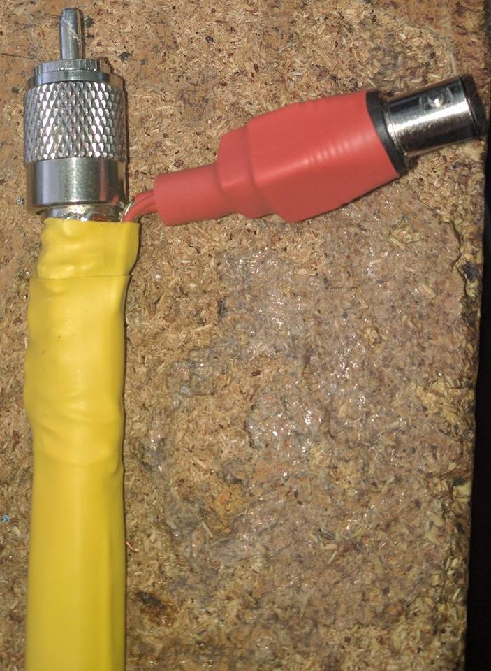
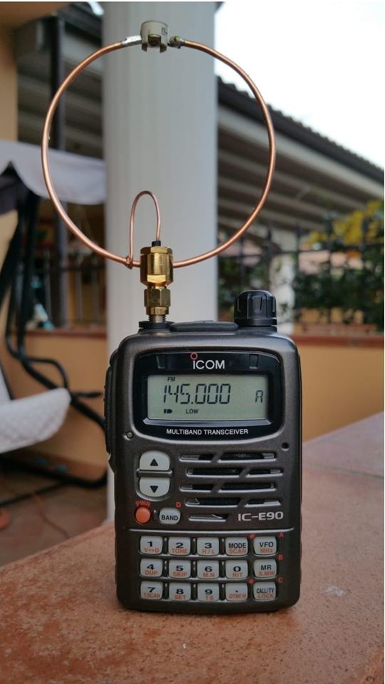
Another style of directional coupler I had worked on.
#EE #electronics #engineering #electicalengineering #rf #radio #ham #hamradio #amateurradio
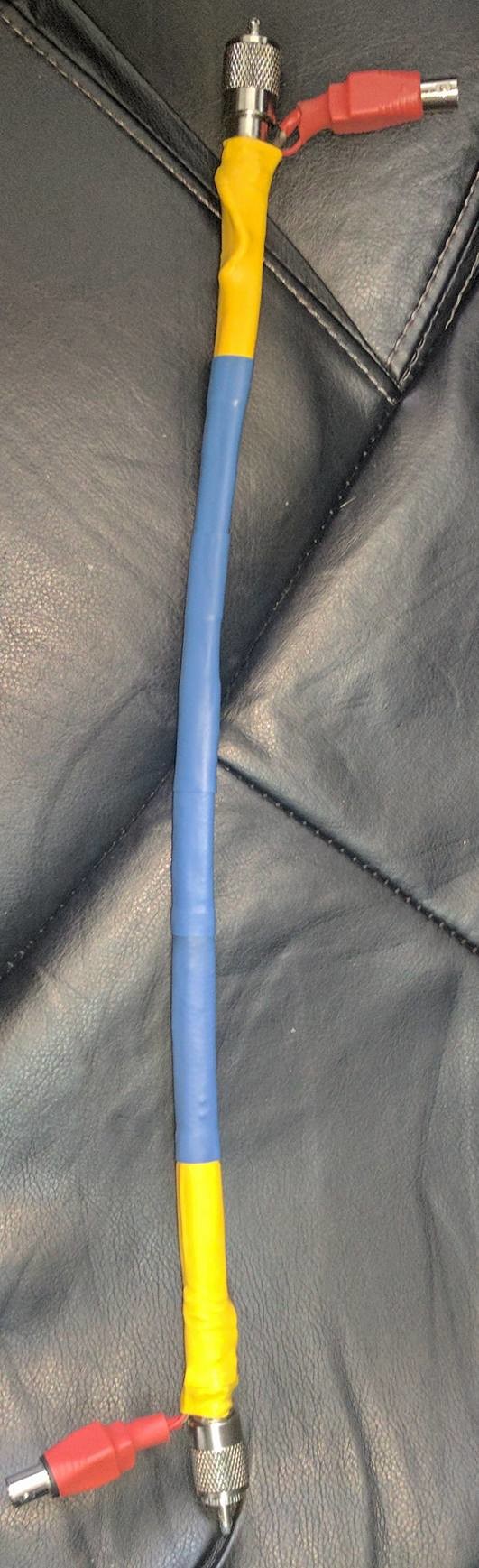
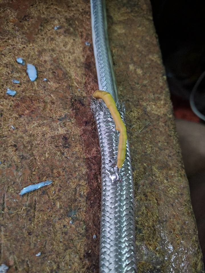
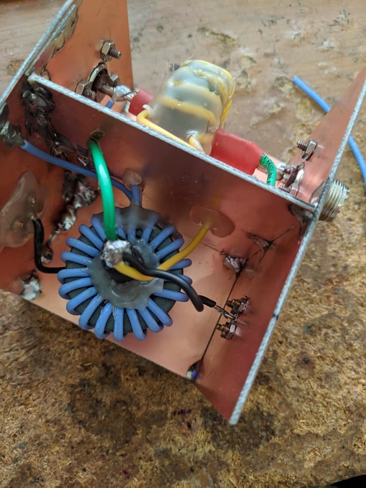
The hardest part of building a directional coupler is seeing how pretty and clean it is and knowing you will need to seal it away with copper walls and it will never be seen by human eyes again.
This was one of the more fun one day projects I ever did.
#EE #electronics #engineering #electicalengineering #rf #radio #ham #hamradio #amateurradio
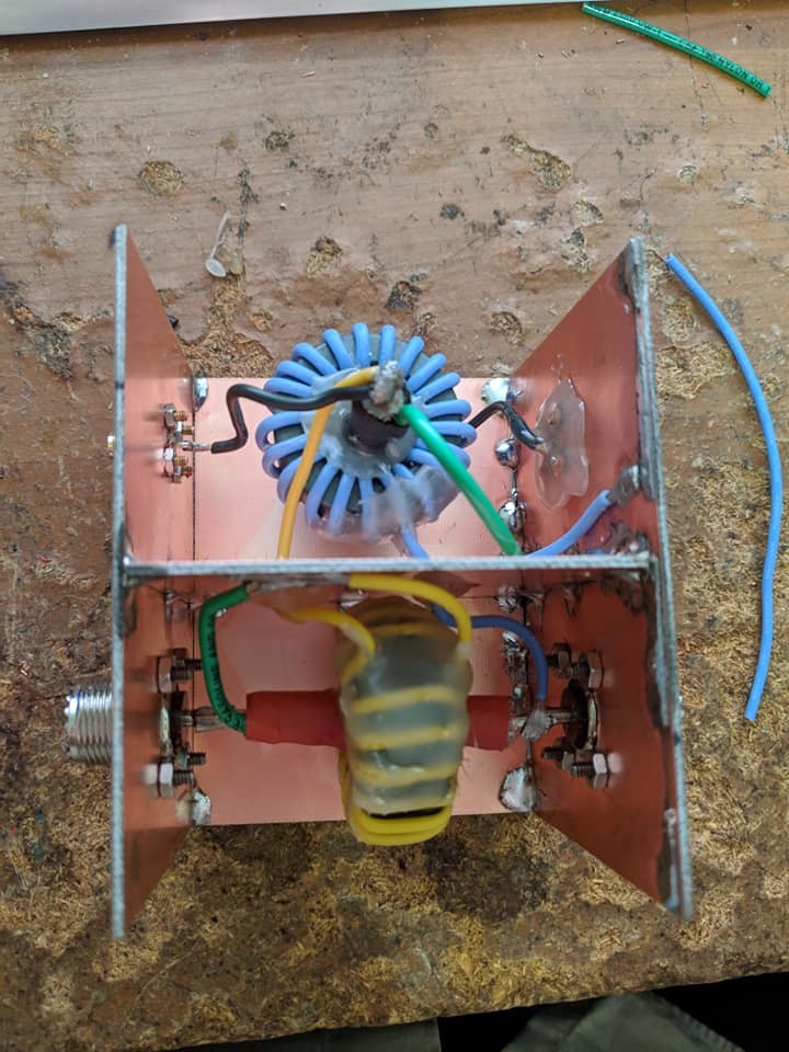
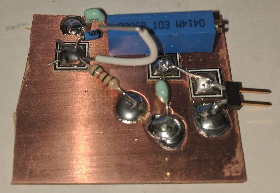
Have I mentioned how much I love doing manhattan style prototyping?
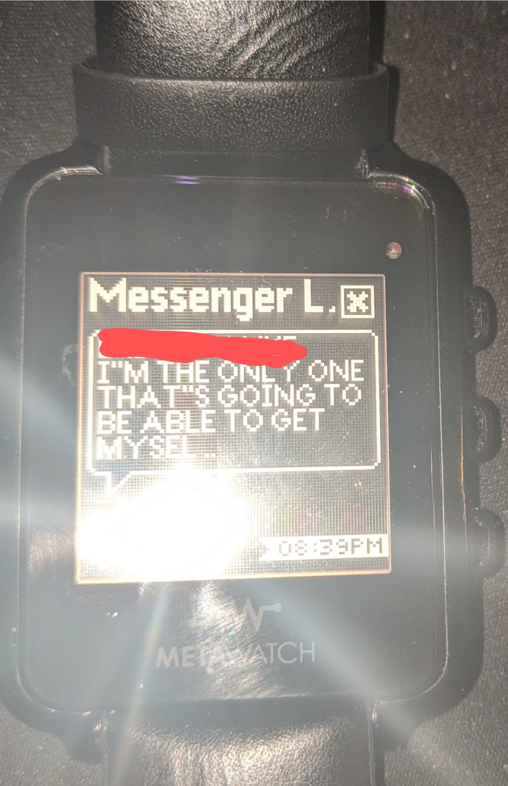
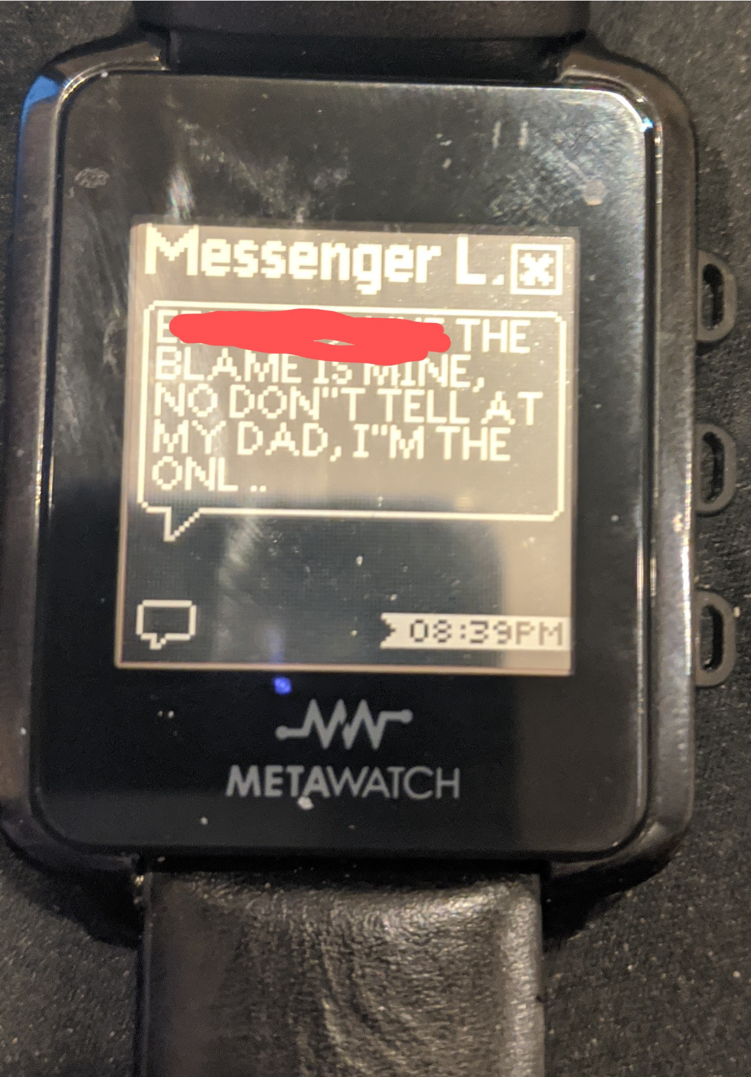
Busted out my super old and now no longer supported metawatch just for shits and giggles. I thought the mirrored back and white lcd front was hella sexy at the time. Still looks pretty sweet.
So while my top-end rig is being repaired i decided to buy a new cheaper rig as a temporary standin. I decided to get a FT-991A. It has a waterfall display and can do digital voice on both HF and VHF/UHF which means it will actually still be useful to me after my main rig is fixed. Looking forward to trying C4FM over HF frequencies!
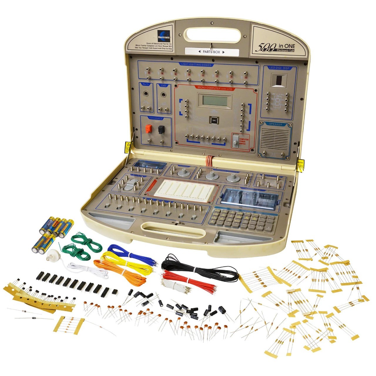
LOL so apparently I just noticed in one of the episodes of Star Trek Enterprise they tried to use one of those Radio Shack 100 in 1 electronics kits as an actual engineering prop. Never picked this up before but omg the lawls.
Also attached a picture of the actual retail device (technically marketed as 500 in 1)
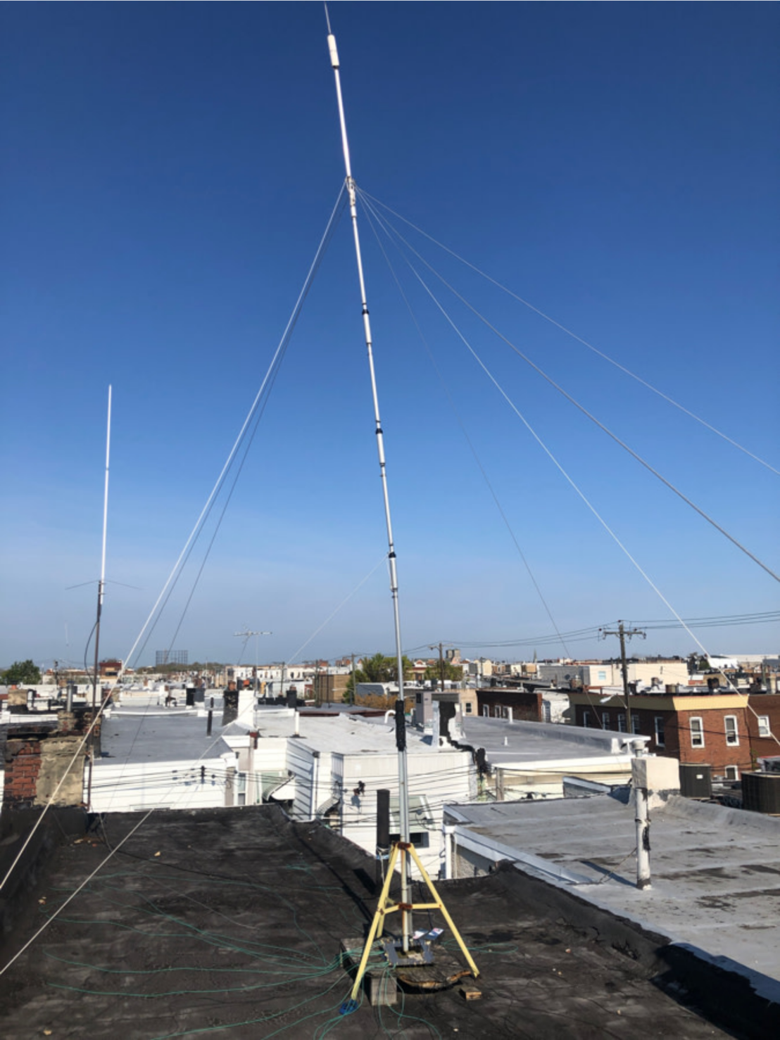
Woot my HF antenna is once again live. Sadly my main hf rig still need ofrepair but i was able to pull out an older rig. I am now transmitting at full 1500watts again! Lightening 0 Jeff 1
- UFoI Member
- http://UFoI.org/u/freemo/
- Website
- http://JeffreyFreeman.me
- Gitlab
- https://git.qoto.org/freemo
Admin
Jeffrey Phillips Freeman
Innovator & Entrepreneur in Machine Learning, Evolutionary Computing & Big Data. Avid SCUBA diver, Open-source developer, HAM radio operator, astrophotographer, and anything nerdy.
Born and raised in Philadelphia, PA, USA, currently living in Utrecht, Netherlands, USA, and Thailand. Was also living in Israel, but left.
Pronouns: Sir / Mister
(Above pronouns are not intended to mock, i will respect any persons pronouns and only wish pronouns to show respect be used with me as well. These are called neopronouns, see an example of the word "frog" used as a neopronoun here: http://tinyurl.com/44hhej89 )
A proud member of the Penobscot Native American tribe, as well as a Mayflower passenger descendant. I sometimes post about my genealogical history.
My stance on various issues:
Education: Free to PhD, tax paid
Abortion: Protected, tax paid, limited time-frame
Welfare: Yes, no one should starve
UBI: No, use welfare
Racism: is real
Guns: Shall not be infringed
LGBT+/minorities: Support
Pronouns: Will respect
Trump: Moron, evil
Biden: Senile, racist
Police: ACAB
Drugs: Fully legal, no prescriptions needed
GPG/PGP Fingerprint: 8B23 64CD 2403 6DCB 7531 01D0 052D DA8E 0506 CBCE
Joined Jul 2018
